background image

4

3.2   4/20mA input

In Europe, sources of energy which do not
generate more than 1.5V; 100mA or 25mW are, for
intrinsic safety purposes, considered to be 

simple

apparatus

 (Clause 5.7 of EN 60079-11).

Although the BA307C and BA308C indicators do
not themselves comply with the requirements for

simple


apparatus

, the EC-Type Examination

Certificate specifies that under fault conditions the
voltage, current and power at the 4/20mA input
terminals 1 & 3 will not exceed those specified for

simple apparatus

.  This allows the BA307C and

BA308C to be connected into any intrinsically safe
circuit protected by a Zener barrier or galvanic
isolator providing the output parameters of the
circuit do not exceed:

Uo

=

30V dc

Io

=

200mA

Po

=

0.85W

The EC-Type Examination Certificate specifies that
the maximum equivalent capacitance and
inductance between the two 4/20mA  input
terminals 1 and 3 is:

Ci

=

20nF

Li

=

10

H

To determine the maximum permitted cable
parameters, these figures should be subtracted
from the maximum cable capacitance and
inductance permitted by the certificate for the loop
into which the indicator is installed.

3.3  Zones, gas groups and T rating

The BA307C and BA308C have been certified as
Group II, Category 1G, EEx ia IIC T5 apparatus at
Tamb –40 to 60

o

C.   When connected to a suitable

system the instruments may be installed in:

Zone 0 explosive gas air mixture

continuously present.

Zone 1 explosive gas air mixture likely to

occur in normal
operation.

Zone 2 explosive gas air mixture not

likely to occur, and if it does
will only exist for a short time.

Be used with gases in groups:

Group   A    propane
Group   B    ethylene
Group   C    hydrogen

Having a temperature classification of:

T1

450

o

C

T2

300

o

C

T3

200

o

C

T4

135

o

C

T5

100

o

C

At ambient temperatures between –40 & +60

o

C.

Note: Operation only specified between –20

o

C and

+ 60

o

C.

This allows both indicators to be installed in all
Zones and to be used with most common Industrial
gases.

WARNING installation in Zone 0

When installed in a Zone 0 potentially
explosive atmosphere requiring apparatus
of Category 1G, the indicator shall be
installed such that even in the event of rare
incidents, an ignition source due to impact
or friction between the aluminium enclosure
at the rear of the instrument mounting panel
and iron/steel is excluded.

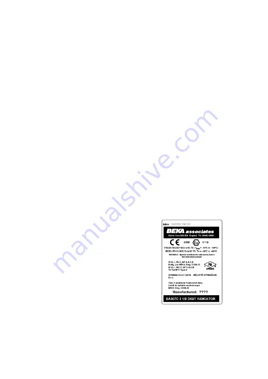
3.4  Certification label information

The certification label is fitted in a recess on the
top outer surface of the enclosure.  It shows the
ATEX certification information, instrument serial
number, year of manufacture plus BEKA
associates’ name and location.  Non European
certification information may also be included.

BA307C certification label

Summary of Contents for BA307C

Page 1: ...Issue 9 22nd March 2013 BA307C BA308C Intrinsically safe loop powered 3 digit panel mounting indicators issue 9 ...

Page 2: ... example 6 6 Over and under range 7 Maintenance 7 1 Fault finding during commissioning 7 2 Fault finding after commissioning 7 3 Servicing 7 4 Routine maintenance 7 5 Guarantee 7 6 Customer comments 8 Accessories 8 1 Scale card 8 2 Tag strip 8 3 Internal calibrator 8 4 Root extractor 8 4 1 Calibration example 8 5 Display backlights 8 5 1 Separately powered 8 5 2 Loop powered Appendix 1 FM cFM Appr...

Page 3: ... and cFM approved for use in Canada these approvals are described in Appendix 1 International IECEx certification is described in Appendix 2 2 OPERATION Fig 1 shows a simplified block diagram of both models The 4 20mA input current flows through resistor R1 and forward biased diode D1 The voltage developed across D1 which is relatively constant is multiplied by a switch mode power supply and used ...

Page 4: ... 1G EEx ia IIC T5 apparatus at Tamb 40 to 60o C When connected to a suitable system the instruments may be installed in Zone 0 explosive gas air mixture continuously present Zone 1 explosive gas air mixture likely to occur in normal operation Zone 2 explosive gas air mixture not likely to occur and if it does will only exist for a short time Be used with gases in groups Group A propane Group B eth...

Page 5: ...r BA308C in a transmitter loop 4 2 Remote indication BA307C and BA308C indicators may be driven via an intrinsically safe interface from a 4 20mA safe area signal to provide a remote indication within a hazardous area The type of interface is not critical either a Zener barrier or a galvanic isolator may be used providing that Uo Io and Po are not exceeded If one side of the 4 20mA current loop ma...

Page 6: ... the panel The indicators may be installed in any instrument panel providing the environmental limits shown in the specification are not exceeded Figs 4A and 4B show the overall dimensions of each instrument and the size of the required panel cut out To achieve an IP65 seal between the instrument enclosure and the instrument panel the smaller tolerance aperture should be used and the BA308C must b...

Page 7: ... Figs 4A and 4B To simplify installation the terminals are removable so that the panel wiring can be completed before the instrument is installed Fig 5 Fitting panel mounting clips 5 3 EMC Both instruments comply with the requirements of the European EMC Directive 2004 108 EEC For specified immunity all 4 20mA wiring should be in screened twisted pairs with the screen earthed within the safe area ...

Page 8: ...uld be calibrated using an external traceable current source with an accuracy greater than 4 A However when verification is not required the indicator can be fitted with an optional internal calibrator which allows rapid calibration without the need for external instruments See section 8 3 for details 6 1 Zero adjustment Zero is defined as the number displayed by the indicator with a 4 000mA input...

Page 9: ...play 25 0 with a 4 000mA input 115 0 with a 20 000mA input i e A zero of positive 250 Ignoring A span of 900 decimal point A decimal point in position 00 0 The following adjustments are required Step 1 The BA307C is required to display a positive zero therefore the suppression elevation links should be put in the elevation position Step 2 The required zero is 250 therefore the zero link should be ...

Page 10: ...aintenance is permitted on intrinsically safe equipment installed in a hazardous area but only certified test equipment should be used unless a gas clearance certificate is available If a BA307C or BA308C fails after it has been functioning correctly the following procedure should be followed Symptom Cause Solution No display and 0V between terminals 1 and 3 No power supply Check that a current is...

Page 11: ...umber is not visible from the front of the instrument after installation 8 3 Internal Calibrator Both indicators can be supplied with an optional internal calibrator which simulates 4 and 20mA input currents This allows rapid calibration without the need for external instruments or disconnection from the 4 20mA input current but it is not a substitute for calibration with a traceable external curr...

Page 12: ...instrument with an internal calibrator Fig 9 Location of clip off link 8 4 1 Calibration example with root extractor The indicator is required to display rate of flow in gallons per minute with a resolution of 0 1 gallons The differential flowmeter has an output of 20mA at a flow rate of 140 0 gallons per minute i e A span of 1400 ignoring the decimal point A decimal point in position 00 0 The fol...

Page 13: ...Certificate specifies that the maximum equivalent capacitance and inductance between terminals 12 and 13 is Ci 0 045µF Li 0 02mH To determine the maximum permitted cable parameters these figures should be subtracted from the maximum permitted cable capacitance and inductance specified by the certificate for the Zener barrier or galvanic isolator powering the backlight Fig 10 Backlight power supply...

Page 14: ... thus significantly reducing the installation cost A shown in Fig 11 the backlight may be connected in series with the indicator Any Zener barrier or galvanic isolator certified EEx ia IIC by a European Notified Body may be used providing the output parameters do not exceed Uo 30V dc Io 200mA Po 0 85W Fig 11 Loop powered backlight Connecting the backlight in series with the indicator will increase...

Page 15: ...8C have a T4 rating at ambient temperatures between 20o C and 60o C and may be used in the following divisions with the following gases Intrinsic Safety Division 1 or 2 Class I Group A B Group C Group D The FM entity parameters are similar to the ATEX parameters The intrinsically safe circuits shown in this manual may therefore be used for installations in the USA providing the Zener barriers and ...

Page 16: ...16 ...

Page 17: ...17 ...

Page 18: ...18 ...

Page 19: ... Conformity number IECEx ITS 05 0002 which specifies the following certification code and marking Ex ia IIC T5 Ta 40o C to 60 o C The specified intrinsic safety parameters are identical to the ATEX safety parameters The IECEx certificate may be downloaded from www beka co uk www iecex com or requested from the BEKA sales office A2 2 Installation The IECEx and ATEX certificates specify identical sa...

Reviews: