12
The accuracy of the internal references, and hence
the display accuracy, will depend upon the
accuracy of the external current source. With a
maximum span of 19999 the indicators have a
display resolution of 0.8µA, we therefore
recommend that the accuracy of the external
current source used for calibration is greater than
0.4µA.
6.8 Function of the P push-button: C - - P
This parameter defines the function of the
P
push-
button when the indicator is in the display mode.
While the button is operated the indicator will
display the input current in milliamps, or as a
percentage of the span.
To check or change the parameter select 'C - -P'
from the main menu and press
P
to reveal the
current setting. Pressing the
Up
or
Down
button
will toggle the setting between '4-20' the current
display and 'PC' the percentage display. When set
as required press
E
to return to the main menu.
Accuracy of the current display depends upon the
accuracy of the internal references which should
be periodically calibrated - see section 6.7.2
6.9 Security code: COdE
The calibration and conditioning of the instrument
may be protected by a four digit security code
which must be entered before access to the
programme menu is granted. New instruments
are programmed with the default security code
0000 which allows unrestricted access to all
programming functions.
To enter a new security code select 'COdE' from
the menu and press
P
which will cause the
indicator to display the current security code. Each
digit of the code can be changed using the
Up
and
Down
push-buttons, and the
P
button to move to
the next digit. When the required code has been
entered press
E
to return to the main menu. The
revised security code will be activated when the
indicator is returned to the operating mode.
If the security code is lost, access to the
programmable functions can be obtained by
moving the internal security link to the override
position. The security code can then be viewed by
selecting 'CodE' from the main menu and pressing
P
.
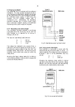
To gain access to the security code link, remove
the instrument control cover, and if fitted unplug
the external switch connector. The security code
override link is located on the inner row of five pins
as shown in Fig 7.
Fig 7 Location of security code override link
6.10 Over and under-range
If the indicator display range is exceeded, the four
least significant digits will be blanked. Under-
range is indicated by '-1' and over-range by '1'.
Under and over-range are also indicated if the
input current falls below approximately 3.5mA or
rises above approximately 21mA.
If the input current falls below 3mA the instrument
initialisation sequence is performed as described in
section 2.

