background image

4

Up

While this button is pushed the
indicator will display the number which
the indicator has been calibrated to
display with a 20mA input.  When
released the normal display in
engineering units will return.

E

No function in the display mode.

3.  TYPE 'nL' CERTIFICATION

3.1 Certificate of Conformity

ITS Testing and Certification Ltd.  (formerly ERA
Technology Ltd) has issued a Certificate of
Conformity Ex99Y4004 confirming that the
BA324ND complies with the CENELEC standard
BS EN50021:1999.    This European standard
specifies the requirements for the construction,
testing and marking of Group II electrical apparatus
with type of protection 'n' intended for use in Zone
2, where an explosive atmosphere of gas is
unlikely to occur, or if it does occur will be
infrequent or remain for short periods only.

3.2 ATEX certification

The BA324ND complies with the European ATEX
Directive 94/9/EC for Group II, Category 3G
equipment.  It has been assessed using the
'Internal Control of Production' procedure specified
in Annex 8 of the Directive.   A technical dossier
has been prepared and an EC Declaration of
Conformity BEKA00ATEX0010 has been issued.

The instrument bears the Community Mark and,
subject to local codes of practice, may be installed
in any of the European Economic Area (EEA)
member countries.   ATEX certificates are also
acceptable for installations in Switzerland.

This manual describes installations which conform
with BS EN60079:Part 14 Electrical Installation in
Hazardous Areas.  When designing systems for
installation outside the UK, the local Code of
Practice should be consulted.

3.3  4/20mA input terminals

Input terminals 1 and 3 may be safely connected in
series with any 4/20mA loop providing that in
normal operation the input current to the indicator
(Ii) does not exceed 30mA  dc.

3.4 Zones, gas groups and T rating

The BA324ND has been certified as Group II,
Category 3G Ex nL IIC T5 apparatus with a Tamb
of -20 to 60°C.

'L' indicates that the BA324ND uses an energy-
limiting technique to achieve compliance as
defined in EN 60079-15.  This technique is based
on the philosophy of 

intrinsic safety

 which limits the

current and voltage applied to components which
may generate a spark in normal operation. e.g.
switches and potentiometers.

These approvals confirm that the BA324ND is 'safe
in normal operation' and may be:

Installed in a Zone 2 hazardous area

Used at ambient temperature between
-20 and +60°C

Used with gases in groups:

Group A

propane

Group B

ethylene

Group C

hydrogen

Used with gases having a temperature
classification of:

T1

450°C

T2

300°C

T3

200°C

T4

135°C

      or

T5

100°C

This allows the  BA324ND indicator to be installed
in Zone 2 low risk hazardous areas, and to be
used with most common industrial gases.

3.5 Certification Label Information

ATEX certification information is shown on a label
fitted in a recess on the top outer surface of the
enclosure.  Non European certification information
may also be included.  The instrument serial
number and date of manufacture are shown on a
separate label inside the terminal compartment.

Summary of Contents for BA324ND

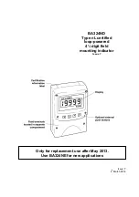
Page 1: ...Issue 7 4th March 2014 BA324ND Type nL certified loop powered 4 digit field mounting indicator Issue 7 Only for replacement use after May 2013 Use BA324NE for new applications...

Page 2: ...eferences 8 Maintenance 8 1 Fault finding during commissioning 8 2 Fault finding after commissioning 8 3 Servicing 8 4 Routine maintenance 8 5 Guarantee 8 6 Customer comments 9 Accessories 9 1 Units o...

Page 3: ...forward biased diode D1 The voltage developed across D1 which is relatively constant is multiplied by a switch mode power supply and used to power the instrument The voltage developed across R1 which...

Page 4: ...60079 Part 14 Electrical Installation in Hazardous Areas When designing systems for installation outside the UK the local Code of Practice should be consulted 3 3 4 20mA input terminals Input terminal...

Page 5: ...Fig 2 BA324ND in a transmitter loop In practice it is only necessary to ensure that in normal operation the maximum current flowing in the loop is less than 30mA In the example shown in Fig 2 this cu...

Page 6: ...ted to the internal EMC filters For maximum radio frequency interference rejection this terminal should be connected to a local earth or to a cable screen which is earthed in the safe area To prevent...

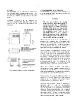
Page 7: ...and may be operated when a flammable atmosphere is likely to be present All the programming functions are contained in an easy to use menu which is shown diagramatically in Fig 6 Each function is sum...

Page 8: ...s the resolution of the least significant display digit May be set to 1 2 5 or 10 digits See section 6 3 d P Decimal point Positions the dummy decimal point between any of the digits or turns it off S...

Page 9: ...ial flowmeter Below 5 of flow the BA324ND display is forced to zero of full flow Current output mA 5 0 4 04 10 0 4 16 25 0 5 00 50 0 8 00 75 0 13 00 100 0 20 00 6 3 Resolution rESn This function defin...

Page 10: ...10...

Page 11: ...least significant digit has been adjusted press E to return to the SPAn prompt followed by E to return to the menu 6 7 Conditioning sub menu Cond This sub menu allows the mains line frequency at whic...

Page 12: ...ith the default security code 0000 which allows unrestricted access to all programming functions To enter a new security code select COdE from the menu and press P which will cause the indicator to di...

Page 13: ...and press E to return to the main menu Step 4 Select frequency of maximum mains line rejection Scroll though the main menu until Cond is displayed Enter the sub menu by pressing P twice and select the...

Page 14: ...y of maximum mains line rejection Scroll though the main menu until Cond is displayed Enter the sub menu by pressing P twice and select the FrE function Using the Up or Down buttons select 50 and then...

Page 15: ...ay has a large voltage ripple content Unable to Incorrect Enter correct security enter the security code or fit security programme code link in override position Mode entered See Fig 7 8 2 Fault findi...

Page 16: ...intenance The mechanical condition of the instrument and electrical calibration should be regularly checked The interval between inspections depends upon environmental conditions We recommend that ini...

Page 17: ...A324ND can also be supplied with a blank or custom engraved stainless steel plate secured to the instrument terminal cover by two screws 9 2 Alarms The BA324ND can be supplied with two solid state sin...

Page 18: ...owing table summarises each of the alarm programme functions and includes a cross reference to more detailed information Again only the functions on alarm 1 are listed but alarm 2 has identical facili...

Page 19: ...een calibrated to display 0 with 4mA input and 10000 with 20mA input the two alarm setpoints may be positioned anywhere between 125 and 10125 To adjust the setpoint select SP1 or SP2 from the alarm me...

Page 20: ...can be changed by pressing the Up or Down button followed by the E button to return to the alarm menu 9 2 8 Hysteresis HStr During programming hysteresis is shown in the units the indicator has been c...

Page 21: ...nt AcSP This function controls a separate menu which provides direct access to the alarm setpoints when the indicator is in the display mode See section 9 2 12 for a full description An operator may t...

Page 22: ...ressing E will return the display to the SP1 or SP2 prompt from which the other setpoint may be selected or the indicator may be returned to the display mode by pressing E again Direct access to the a...

Page 23: ...n can be selected using the Up and Down push buttons The delete break point function dEL operates in a similar manner to the Add function described above When the required number of break points has b...

Page 24: ...24...

Page 25: ...equired break point has been selected press P to reveal the existing display Using the Up and Down buttons and P to move between digits set the revised display Press E to return to the sub menu from w...

Page 26: ...i 30V dc Ii 100mA dc Pi 1 3W This allows the backlight to be powered from a safe area 18 to 30V dc supply as shown in Fig 15 Providing the supply voltage is less than 30V the backlight safety componen...

Page 27: ...re available for securing the BA324ND to a horizontal or vertical pipe BA392D Stainless steel bracket secured by two worm drive hose clips Will clamp to any pipe with outside diameter between 60 and 8...

Reviews: