8
If the correct code has been entered pressing
E
will cause the first parameter 'root' to be displayed.
If an incorrect code is entered the indicator will
return to the display mode.
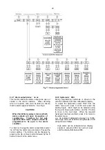
Once within the menu the required parameter can
be reached by scrolling through the main menu
using the
Up
and
Down
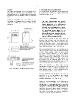
push-buttons as shown in
Fig 6. When returning to the display mode
following recalibration or changes to any
parameters, the indicator will display circulating
decimal points for a few seconds while the new
information is stored in permanent memory.
All new BA324ND indicators are supplied
calibrated as requested at the time of ordering. If
calibration is not requested, the indicator will be set
to display 0.00 with 4mA input, and 100.00 with
20mA input, but can easily be re-calibrated on-site.
6.1 Summary of programmable functions
This section summarises all of the programmable
functions and when read in conjunction with Fig 6
provides sufficient information to condition and
calibrate the indicator. A cross-reference to more
information is given for each function.
Display
Description of function
'root'
Square root extractor
Turns the square root extractor for
linearising the output from differential
flowmeters 'On' or 'OFF'. This function
is omitted when a lineariser is
installed.
See section 6.2
'rESn'
Display resolution
Selects the resolution of the least
significant display digit. May be set to
1, 2, 5 or 10 digits.
See section 6.3
'd.P.'
Decimal point
Positions the dummy decimal point
between any of the digits or turns it
off.
See section 6.4
Display
Description of function
'CAL'
Calibration of display using
external current source.
Enables the zero and span of the
indicator to be adjusted using an
external current source such as a
calibrator. Also enables a complete
loop to be calibrated from primary
element to the indicator display.
When used with an accurate
traceable current source this is the
preferred method of calibration.
See section 6.5
'SEt'
Calibration of display using internal
references.
Enables the zero and span of the
indicator to be adjusted without the
need for an accurate input current or
disconnection from the 4/20mA loop.
See section 6.6
'Cond'
Indicator conditioning
This function provides access to a
sub-menu enabling the mains (line)
frequency rejection to be selected and
the internal references to be
calibrated. Because these
parameters will alter the indicator
display, they are contained in a sub-
menu to prevent inadvertent
adjustment.
Caution
If the mains filter frequency
is changed, the indicator
display and internal
references (if used) must be
recalibrated.
See section 6.7
'FrE'
Frequency rejection
Defines the mains (line) frequency at
which the indicator has maximum ac
rejection. 50 or 60Hz may be
selected. This function must be set
before the instrument is calibrated as
it effects the indicator display.
See section 6.7.1

