3
1.
DESCRIPTION
The BA326C is an intrinsically safe, panel
mounting, loop powered 4/20mA combined
bargraph and digital indicator.
The one
hundred segment bargraph provides a quick
indication of input current magnitude and
trend, supported by an accurate digital display
which may be calibrated in engineering units.
The
BA326C
is
a
second
generation
instrument which, although having additional
functions, remains compatible with the original
BA326B.
The main application of the BA326C is to
display a measured variable or control signal in
a hazardous process area. The zero and span
of the digital display are independently
adjustable so that the indicator may be
calibrated to display any 4/20mA variable in
engineering units.
The analogue display
shows the 4/20mA input on a single or double
100 segment bargraph which may be fitted
with a custom scale to indicate the units of
measurement.
Both the bargraph and digital
display may be offset to indicate deviation from
a specified input current.
The BA326C and the optional accessories
have been certified intrinsically safe for use in
gas hazardous areas by Notified Body Intertek
Testing and Certification Ltd. This certification
has been used to confirm compliance with the
European ATEX Directive 2014/34/EU.
The EC-Type Examination Certificate specifies
that under fault conditions the output voltage,
current and power at input terminals 1 and 3
will not exceed those specified for
simple
apparatus
in Clause 5.7 of EN60079-11.
This instruction manual describes ATEX
certification for BA326C instruments with serial
numbers above 071235/01/001. International
IECEx certification is described in Appendix 1.
BA326C indicators with serial numbers above
071235/01/001 are not FM approved.
The BA326C indicator is housed in a robust
144 x 48 panel mounting DIN enclosure with
an IP65 sealed front.
2.
OPERATION
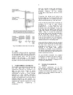
Fig 1 shows a simplified block diagram of a
BA326C.
The 4/20mA input current flows
through resistor R1 and forward biased diode
D1. The voltage developed across D1, which
is relatively constant, is multiplied by a switch
mode power supply and used to power the
instrument. The voltage developed across R1,
which is proportional to the 4/20mA input
current, provides the input signal for the
analogue to digital converter.
Each time a 4/20mA current is applied to the
instrument, initialisation is performed. After a
short delay the following display sequence
occurs:
Firmware
In form x.xx version
displayed.
-1.8.8.8.
Display test in which
all segments of the
display are activated.
Input current
Using calibration
display in
information stored in
engineering instrument
memory.
units.
Fig 1 Simplified block diagram of BA326C
Summary of Contents for ba326c
Page 11: ...11...


