5
3.3
Zones, gas groups and T rating
The
BA326C
has
been
certified
Ex ia IIC T5 Ga. When connected to a suitable
system the indicator may be installed in:
Zone 0
explosive gas air mixture
continuously present.
Zone 1
explosive gas air mixture likely
to occur in normal operation.
Zone 2
explosive gas air mixture not
likely to occur, and if it does
will only exist for a short time.
Be used with gases in groups:
Group
A
propane
Group
B
ethylene
Group
C
hydrogen
Having a temperature classification of:
T1
450
o
C
T2
300
o
C
T3
200
o
C
T4
135
o
C
T5
100
o
C
This allows the BA326C to be installed in all
Zones and to be used with most common
industrial gases.
The BA326C ATEX EC-Type Examination
Certificate number has an X suffix indicating
that special conditions for safe use apply when
installed in Zone 0.
These are explained
below.
WARNING installation in Zone 0
When installed in a Zone 0 potentially
explosive
atmosphere
requiring
apparatus of Category 1G, the indicator
shall be installed such that even in the
event of rare incidents, an ignition
source due to impact or friction between
the aluminium enclosure at the rear of
the instrument mounting panel and
iron/steel is excluded.
3.4
Certification label information
The certification label is fitted into a recess on
the side of the instrument enclosure. It shows
the ATEX certification information, year of
manufacture and the instrument serial number.
BEKA associates name and address are also
shown. Non European certification information
may also be included.
4.
SYSTEM DESIGN FOR HAZARDOUS
AREAS ATEX CERTIFICATION
4.1
Transmitter loops
A BA326C indicator may be connected in
series with almost any intrinsically safe 4/20mA
current loop and calibrated to display the
measured
variable
or
control
signal
in
engineering units. There are two basic design
requirements:
1.
The intrinsic safety output parameters of
the 4/20mA loop, which are defined by
the Zener barrier(s) or galvanic isolator,
must be less than:
Uo
28V dc
Io
200mA
Po
0.84W
2. The loop must be able to tolerate the
additional 1.1V required to operate the
indicator (increases to 1.2V at -20ºC).
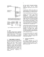
Fig 2 illustrates a typical application in which a
BA326C is connected in series with a 2-wire
transmitter protected by a Zener barrier.
Summary of Contents for ba326c
Page 11: ...11...


