7
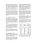
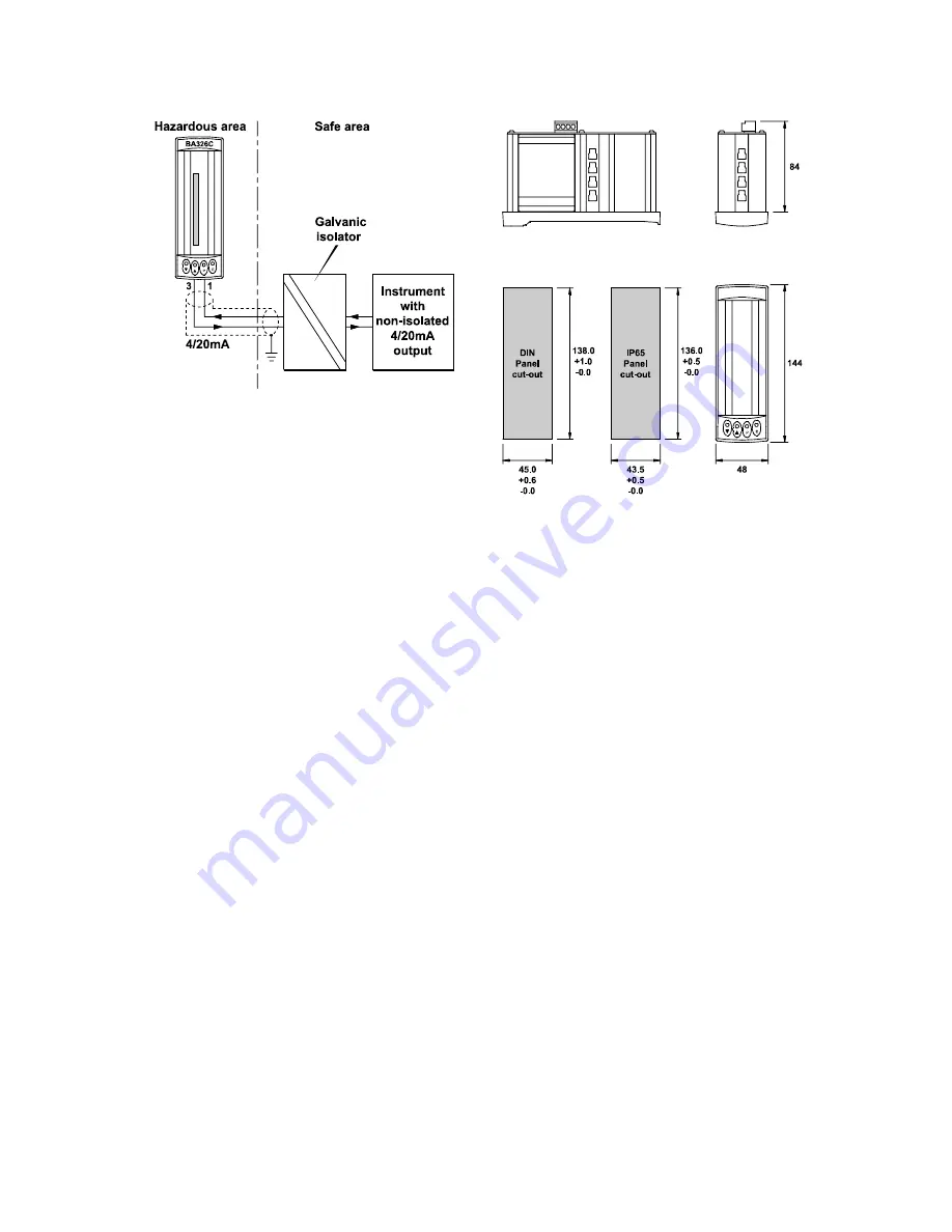
Fig 3C Galvanic isolator can be used with any
4/20mA current loop.
5.
INSTALLATION
5.1
Location
The BA326C indicator is housed in a robust
aluminium enclosure with an armoured glass
window surrounded by a Noryl bezel.
The
front
of
the
instrument
provides
IP65
protection, and a gasket seals the joint
between the instrument enclosure and the
panel. The instrument may be installed in any
panel providing the environmental limits shown
in the specification are not exceeded.
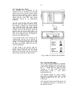
Fig 4 shows the overall dimensions of the
BA326C and panel cut-out.
To achieve an
IP65 seal between the instrument enclosure
and the panel the smaller cut-out must be used
and the instrument secured with four mounting
clips.
The BA326C liquid crystal display has
maximum contrast when viewed from directly
ahead and slightly below the centre line of the
instrument.
For reflective displays there is
very little degradation of contrast when viewed
from above the centre line, but slight
degradation may be noticeable when the
instrument is fitted with a backlight.
Fig 4 BA326C dimensions
5.2
Installation Procedure
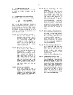
Fig 5 illustrates the instrument installation
procedure.
a. Insert the BA326C into the instrument
panel from the front of the panel.
b. Fix panel mounting clips to the sides of
the BA326C and tighten until the
instrument is secure - see Fig 5.
Recommended torque 22cNm (1.95 lbf
in)
Do not over tighten
. If an IP65 seal
is required between the enclosure and
the
instrument
panel,
four
panel
mounting clips must be used.
c. Connect the panel wiring to the rear
terminal block(s) as shown in Fig 5. To
simplify installation the terminals are
removable so that the wiring can be
completed before the instrument is
installed.
Summary of Contents for ba326c
Page 11: ...11...


