8
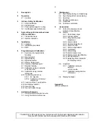
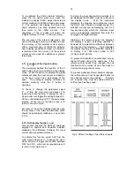
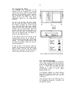
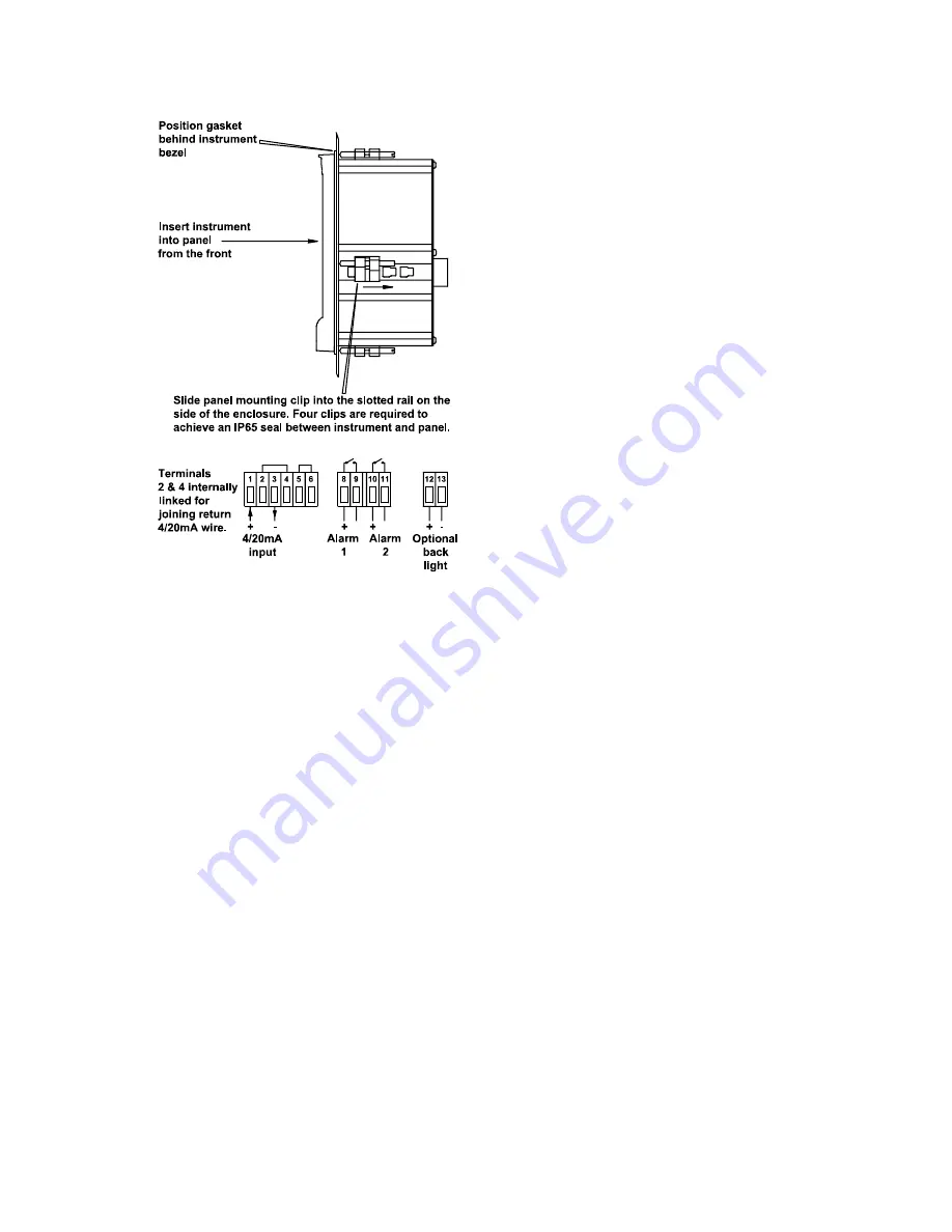
Fig 5 Installation and terminal connections
5.3
EMC
The BA326C complies with the requirements
of the European EMC Directive 2014/30/EU.
For specified immunity all wiring should be in
screened twisted pairs, with the screens
earthed in the safe area.
The indicator
enclosure may be earthed locally by putting a
tag under one of the rear panel fixing screws.
6.
PROGRAMMING & CALIBRATION
The BA326C is programmed and calibrated via
four front panel push buttons. All the
programming functions are contained in an
easy
to
use
menu
which
is
shown
diagramatically in Fig 6.
Each function is
summarised in section 6.1 which includes
references to more detailed information.
Although this simple menu driven system
enables most adjustments to be made without
repeated reference to this manual, it is
recommend that at least the summary of the
programmable functions in section 6.1 is read
before
attempting
programming
or
recalibration.
When the indicator is fitted with linearisation,
the basic menu is expanded to include
additional
functions.
All
the
optional
accessories are described in section 9 of this
manual.
Throughout this manual push buttons are
shown in italics e.g.
P
or
Up
push button, and
legends displayed by the indicator are shown
within inverted commas e.g. 'CAL' and ' ALr2'.
Access to the programme menu is obtained by
operating
the
P
and
E
push
buttons
simultaneously.
If the instrument is not
protected by a security code the first
parameter 'root' will be displayed. If a security
code other than the default code 0000 has
already been entered, the indicator will display
'COdE'. Press
P
to clear this prompt and
enter the security code for the instrument using
the
Up
,
Down
and
P
push buttons.
If the
correct code has been entered pressing
E
will
cause the first parameter 'root' to be displayed.
If an incorrect code or no entry is made the
indicator will return to the display mode.
Once within the programme menu the required
parameter can be reached by scrolling through
the main menu using the
Up
and
Down
pushbuttons as shown in Fig 6.
When
returning to the display mode following
recalibration or changes to any parameters,
the indicator will display circulating minus signs
for a few seconds while the new information is
stored in permanent memory.
All new BA326C indicators are supplied
calibrated as requested at the time of ordering.
If calibration is not requested, the digital
indicator will be calibrated to display 0.00 to
100.00 for 4 to 20mA input.
6.1
Summary of programmable
functions
This
section
summarises
all
of
the
programmable functions and when read with
Fig 6 provides sufficient information to
condition and calibrate the indicator. A cross-
reference to a more detailed description is
given for each function.
Summary of Contents for ba326c
Page 11: ...11...


