background image

20

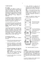
Step 6

Enter the rate timebase

Select ‘t-bASE’ from the main menu
and press 

P

 to show the current

setting.  In this example the rate
display is required in litres per hour.
Using the 

Up

 or 

Down

 button scroll

through the three options and
select ‘tb-3600’ which will multiply
the rate display by 3600. Return to
the ‘t-bASE’ prompt in the main
menu by pressing 

E

.

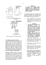
Step 7

Adjust the rate filter

The rate display filter parameters
should be adjusted experimentally
after installation to provide a stable
rate display with an acceptable step
response.

During commissioning it is
recommend that initially the second
digit of the rate parameters is set to
0 (step response off) while the first
digit (amount of filtering) is adjusted
to provide acceptable rate display
stability. The second digit should
them be increased until acceptable
rate display stability is once again
achieved.

To adjust the filter parameters
select ‘FILtEr’ from the main menu
and press 

P

 to reveal the current

setting.  The first digit will be
flashing and may be adjusted using
the 

Up

 or 

Down 

button.  The 

P

button will transfer control to the
second digit.  When both are set as
required, return to the ‘FILtEr’
prompt in the main menu by
pressing 

E

.

   Note:

  While adjusting the filter, the rate is

shown on the lower display so that
stability can be assessed.

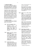
Step 8    Enter the total scaling factor

The K factor of the flowmeter in this
example is 105.0 pulses per litre
and the total display is required in
cubic metres.

There are 1000 litres in a cubic
metre so the BA344D is required to
display 1 cubic metre for every 105
x 1,000 pulses received.  ‘SCALE-t’
should therefore be set to 105,000

Select ‘SCALE-t’ from the main
menu and press 

P

 which will reveal

the current setting with one digit
flashing. To position the decimal
point, operate the 

P

 push-button to

move the flashing digit to the least
significant position.  Pressing the

Up

 and 

Down

 buttons

simultaneously will then remove the
decimal point.
Using the 

Up

 and 

Down

 buttons to

adjust each digit in turn and the 

P

button to transfer control between
digits, enter 105000  -  Finally
return to the 'SCALE-t' prompt in
the main menu by pressing 

E

.

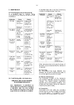
Step 9

Define clip-off

In this example totalisation is to be
inhibited at flow rates below 1 litre
per minute.

Select ‘CLIP-OFF’ from the main
menu and press 

P

 which will reveal

the clip-off threshold in litres per
hour i.e. the same units already
selected for the rate display.  The
most significant digit of the display
will be flashing indicating that this
digit may be adjusted.   Pressing P
five times will move the flashing
digit to the third least significant
position.

Using the 

Up

 and 

Down

 buttons set

the second least significant digit to
6  i.e. a clip-off threshold of 60 litres
per hour (1 litre per minute).
Finally return to the 'CLIP-OFF'
prompt in the main menu by
pressing 

E

.

.

Step 10 Turn local reset on

In this example the operator needs
to reset the total display to zero by
pressing the 

Up

 and 

Down

 buttons

simultaneously.  To activate the
local reset function select
‘LOC.rSEt’ from the main menu and
press 

P

 to display the current

setting.  Pressing the 

Up

 or 

Down

button will toggle the display
between ‘On’ and ‘OFF’.  Select
‘On’ and press 

E

 to return to the

‘LOCrSEt’ prompt in the main
menu.

Summary of Contents for BA344D

Page 1: ...Issue 5 7th April 2009 BA344D Intrinsically safe Battery powered pulse input field mounting rate totaliser Issue 5...

Page 2: ...0 Rate filter 6 11 Total scale factor 6 12 Clip off 6 13 Local reset 6 14 Resetting grand total 6 15 Security code 7 Calibration Example 7 1 Calibration procedure 8 Maintenance 8 1 Fault finding durin...

Page 3: ...es or via the optional external keypad Optional alarms which may be programmed to function on the rate or total displays further extend the applications of this instrument The BA344D contains an inter...

Page 4: ...mospheres which conform with BS EN60079 Part14 2003 Electrical Installation in Hazardous Areas When designing systems for installation outside the UK the local Code of Practice should be consulted For...

Page 5: ...and 4 is Ci 30nF Li 10 H To determine the maximum permissible cable parameters these figures should be subtracted from the maximum permitted cable parameters specified for the device connected to ter...

Page 6: ...perated simultaneously See 6 13 Each time the total display is reset to zero the grand total is transferred to permanent memory 3 5 Zones gas groups and T rating The BA344D has been issued with an EC...

Page 7: ...onnected to terminals 5 6 The maximum input counting frequency is 10kHz 4 1 System certificates When the input signal is derived from the safe area or the total display is to be reset from within the...

Page 8: ...rconnected within the BA344D see Fig 1 4 3 Use with Galvanic Isolators Galvanic isolators are probably the simplest intrinsically safe interface as they provide isolation and do not require a high int...

Page 9: ...nstallation procedure a Remove the instrument terminal cover by unscrewing the two captive A screws b Mount the instrument on a flat surface and secure with two M6 screws through the B holes Alternati...

Page 10: ...ssembly The discharged battery may be removed and the replacement fitted while the BA344D rate totalisers is installed in the hazardous area Fig 7 illustrates the replacement sequence a If the instrum...

Page 11: ...the instrument enclosure Before replacing the terminal cover turn the instrument ON by moving the slide switch to the right Fig 7 Replacement of internal battery 5 5 Disposal of used batteries The BEK...

Page 12: ...ond minute or hour Similarly to calculate the total flow in the required units of measurement the number of input pulses is divided by the total scale factor SCALE t Total flow is continuously added t...

Page 13: ...13...

Page 14: ...section 6 6 dISPLAY 2 Lower display Turns the lower display which normally shows rate on or off See section 6 7 Display Description of function SCALE r Rate Scale Factor Defines the arithmetic relatio...

Page 15: ...ype select InPut from the menu and press P which will reveal the current input type Pressing Up or Down will scroll through the four options UOLts Voltage pulse input Threshold 1V and 3V 10kHz max Inp...

Page 16: ...int position and simultaneously press the Up and Down buttons When the required rate scale factor has been entered press E to store the number and return to the main menu 6 9 Timebase t bASE The timeb...

Page 17: ...ecimal point in the scale factor move the flashing digit to the left hand side of the required decimal point position and simultaneously press the Up and Down buttons When the required total scale fac...

Page 18: ...d before access to the programme menu is granted New instruments are programmed with the default security code 0000 which allows unrestricted access to all programming functions without entering a sec...

Page 19: ...3 Select the type of input Using the Up or Down button scroll through the main menu until InPut is displayed then press P to reveal the existing setting Select COIL the input for a magnetic pick off u...

Page 20: ...A344D is required to display 1 cubic metre for every 105 x 1 000 pulses received SCALE t should therefore be set to 105 000 Select SCALE t from the main menu and press P which will reveal the current...

Page 21: ...rument to the CLr Gtot prompt in the main menu Step 12 Define the security code Defining a security code prevents unauthorised access to the programme functions Select COdE from the main menu and pres...

Page 22: ...equipment should be used unless a gas clearance certificate is available If a BA344D fails after it has been functioning correctly the following table may help Symptom Cause Check No display Instrume...

Page 23: ...larm annunciators on the instrument display indicate the status of both alarms If an alarm delay or silence time has been selected the annunciator will flash during the delay or silence period Program...

Page 24: ...lay Description of function EnbL Alarm enable Enables or disables the alarm function without changing the alarm parameters See section 9 2 4 tYPE Type of alarm Defines whether the alarm operates on th...

Page 25: ...rn to the alarm menu 9 2 5 Type of alarm tYPE Alarm 1 and Alarm 2 may both be rate or total alarms or one may be conditioned for rate and the other for total To check or change the type of alarm selec...

Page 26: ...select HStr from the alarm menu and press P which will reveal the existing figure Each digit can be adjusted using the Up and Down push buttons and the P button to move to the next digit When the req...

Page 27: ...o the setpoints in the display mode by pressing the P and Up buttons simultaneously New instruments with alarms are supplied with the security code set to 0000 9 2 13 Adjusting alarm setpoints from th...

Page 28: ...mounting kits are available for securing the BA344D to a horizontal or vertical pipe BA392D Stainless steel bracket secured by two worm drive hose clips for 60 to 80mm outside diameter pipes BA393 He...

Page 29: ...ertification Appendix 1 EnbL 9 2 3 9 2 4 Fault finding during commissioning 8 1 after commissioning 8 2 FILtEr 6 10 Flow indicator 2 2 Galvanic isolators 4 3 Gas groups 3 5 Grand total 2 2 clear 6 14...

Page 30: ...ve atmosphere in the form of a cloud of combustible dust in air is likely to occur occasionally in normal operation Zone 22 explosive atmosphere in the form of a cloud of combustible dust in air is no...

Page 31: ...ctioning immediately it is switched on When a replacement battery is fitted or when the rate totaliser is turned on after not being used for an extended period the battery should be conditioned by dra...

Reviews: