38
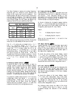
This should be changed to 4.5461 using
the
&
or
*
push button to adjust the
flashing digit and the
(
button to
transfer control to the next digit and to
position the decimal point. Finally, enter
the new value and return to the
5CALE
.
r-A
prompt in the configuration
menu by pressing
)
.
The flow rate display is independent of
the total flow display.
Repeat for input b using the
5CALE
.
r-b
function.
See 6.15
Step 12 Enter the rate timebase
The rate timebase determines if rate is
displayed per second, per minute or per
hour. In this example gallons per hour
are required. Using the
&
or
*
push
button select
t-bA5E
from
the
configuration menu and press
(
. Again
using the
&
or
*
push button select
tb-3600
from the three options which will
multiply the rate display by 3600. Enter
the selection and return to the
t-bA5E
prompt in the configuration menu by
pressing
)
.
See 6.16
Step 13 Adjust the display filter
The digital display filter has two
independent adjustable parameters
enabling the rate display response to be
tailored for optimum performance. The
filter parameters are controlled by a two
digit number. The first digit defines the
amount of filtering applied to the display,
for initial configuration it is recommended
it is set to 2 which is a time constant of
4.3 seconds. The second digit controls
jump-out following a step input change
and it is recommended that this is initially
set to 0.
After configuration during commissioning
both parameters should be adjusted
experimentally to provide a stable display
with an acceptable step response. To
allow the effect of filter changes to be
seen immediately, the live rate display is
shown on the lower display while the
filter parameters are shown and may be
adjusted on the upper display.
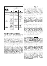
Using the
&
or
*
push button select
FiLtEr-A
from the configuration menu
and press
(
. The first digit, which
controls the filter time constant, will be
flashing and should be set to
2
using the
&
or
*
push button. The
(
button
will transfer control to the second digit,
which controls the step response and
should be set to
0
in the same way.
Finally, enter the selection and return to
the
FiLtEr
prompt in the configuration
menu by pressing
)
.
Repeat for input b using the
FiLtEr-b
function.
See 6.17
Step 14 Define clip-off
To prevent totalisation of low flow rates
clip-off defines an adjustable flow rate
threshold below which totalisation is
inhibited. In this example it is required
that totalisation does not occur at flow
rates below 10 gallons per hour on each
input.
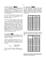
Using the
&
or
*
push button select
CLP
.
oFF-A
from the configuration menu.
Press
(
which will reveal the existing
clip-off threshold in gallons per hour i.e.
the same units already selected for the
rate display. Change the display to
10
using the
&
or
*
push buttons to
adjust the flashing digit and the
(
button to transfer control to the next
digit. Finally, enter the new clip-off
threshold and return to the
CLP
.
oFF-A
prompt in the configuration menu by
pressing
)
.
Repeat for input b using the
CLP
.
oFF-b
function.
See 6.18
Step 15 Local reset of total and grand total
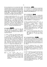
Two separate functions in the
LoC,clr
sub-menu may be individually activated
to allow the operator to reset the
individual totals and the composite grand
total displays from the totalising mode
without entering the configuration menu.
In this example the operator is required
to reset the total displays but not the
composite grand total display when the
BA384NG Rate Totaliser is in the
totalising mode.

