5
b.
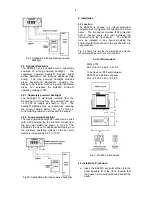
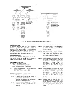
Fix two panel mounting clips to opposite
sides of the instrument and tighten until the
indicator is secured as shown in Fig 4.
c.
Connect the panel wiring to the rear terminal
block(s) as shown in Fig 3. To simplify
installation, the terminals are removable so
that the panel wiring can be completed
before the instrument is installed.
Fig 4 Fitting panel mounting clips
4.3 EMC
The BA505C complies with the requirements of
the European EMC Directive. For specified
immunity all wiring should be in screened twisted
pairs. The indicator enclosure may be earthed
locally by securing a tag under one of the rear
panel corner fixing screws.
5. Calibration
The front panel multi-turn control adjusts the set
point station’s output current between
approximately 3.5 and 21mA, no calibration is
required.
5.1 Internal display
The BA505C internal display may be calibrated so
that the 4/20mA loop current is shown in the
required engineering units.
The BA505C display will be supplied calibrated as
requested at time of ordering. If calibration is not
requested, the display will be set to show 00.0
with 4.000mA loop current, and 100.0 with
20.000mA loop current, but may easily be
recalibrated on-site.
The display is calibrated by plug-in links and two
multi-turn potentiometers that are accessible
through holes in the rear panel. To gain access
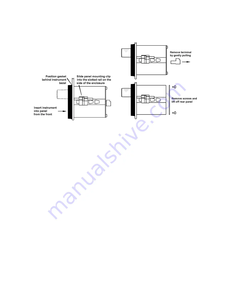
to the links the rear panel must be removed as
shown in Fig 5.
For maximum accuracy the display should be
calibrated using a traceable current measuring
device with an accuracy greater than 4µA.
Fig 5 Removal of rear panel
5.2 Zero adjustment
Zero is defined as the number displayed with a
4.000mA loop current, and may be adjusted
between -1000 and 1000. The zero
potentiometer has two ranges, 0 to 500 and 500 to
1000; the polarity of the zero is defined by the
position of the suppression / elevation links.
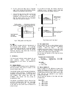
Fig 6 shows the position of the links and zero
potentiometer.
Suppression / elevation links
Elevation
Positive zero
0 to 1000
or
Suppression
Negative zero
0 to -1000
Zero link
0 to 500
or
500 to 1000
5.3 Span adjustment
Span is defined as the difference between the
number displayed at 4.000mA and the number
displayed at 20.000mA loop current. The span
potentiometer has four ranges defined by the span
links, and may be adjusted to any number
between 0 and 1999.
Fig 6 shows the position of the links and span
potentiometer.
Span links
000 to 500
or
500 to 1000
or
1000 to 1500
or
1500 to 1999

