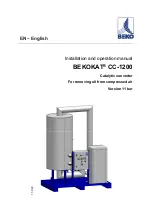
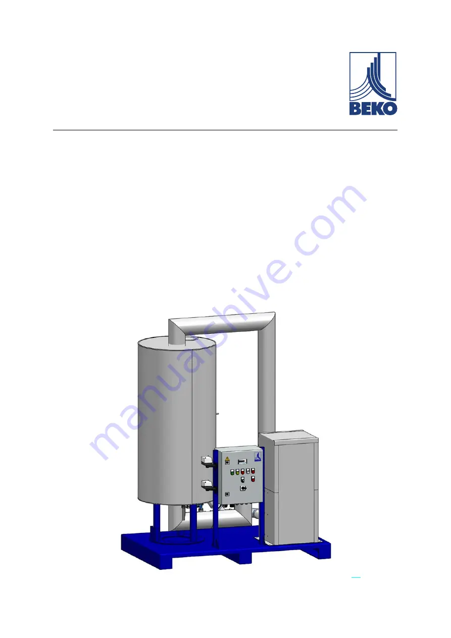
background image


EN – English


Installation and operation manual 

BEKOKAT

®

 CC-1200 

Catalytic converter 

For removing oil from compressed air 

Version 11 bar  


11-0

43


Summary of Contents for BEKOKAT CC-1200

Page 1: ...EN English Installation and operation manual BEKOKAT CC 1200 Catalytic converter For removing oil from compressed air Version 11 bar 11 043 ...

Page 2: ...on 01 Document No 11 043 Dear customer Thank you for purchasing the BEKOKAT CC 1200 Catalytic Converter Please follow our instructions and read this installation and operation manual carefully before installing and comissioning the catalytic converter The proper function of the catalytic converter can only be guaranteed when the described regulations and instructions are strictly observed ...

Page 3: ...s 22 2 2 Transport 24 2 3 Requirements for the site 25 Product information and system description 26 3 1 Type plate 26 3 2 Product view 27 3 3 Function description of the catalytic converter 28 3 4 Set up Description 30 3 5 Description of the components 31 3 5 1 Heat exchanger plate 1 31 3 5 2 Catalytic converter reactor 2 31 3 5 3 Temperature Control Unit 3 31 3 5 4 Heating system 4 32 3 5 5 Incl...

Page 4: ...MERGENCY STOP device 54 Commissioning 55 5 1 Safety instructions 55 5 2 Inspection before commissioning 57 5 3 Operation 58 5 3 1 Electric control 59 5 3 2 Settings 60 5 4 Initial commissioning 61 5 5 Notes on the reactor temperature during commissioning 63 5 6 Notes on the operation of the BEKOKAT 65 5 7 Notes on reactor temperature during operation 66 5 8 Re commissioning after shut down 67 Trou...

Page 5: ... Maintenance 78 7 1 Safety instructions 78 7 2 Decommissioning for service maintenance or repair 80 7 3 Maintenance schedule 81 7 4 Recurring inspections 82 7 5 Exchange of catalyst agent 83 7 6 Waste code 83 Disposal 84 8 1 Decommissioning 84 8 2 Disposal 84 Appendix 85 Service addresses 88 ...

Page 6: ... the start of all work installation commissioning and maintenance A prerequisite for safe handling and trouble free operation of this plant device is compliance with all stated safety instructions and handling instructions The operating instructions are an integral part of the system and must be available at all times at the location of use of the BEKOKAT The local accident prevention regulations ...

Page 7: ... in the operating manual before an action work activity is described which can create a hazard General hazard symbols danger warning caution Warning about electric voltage Warning about hot surfaces General instructions The installation and operation manual guidelines must be strictly adhered to Wear eye protection Wear safety shoes Wear protective clothing Information for fire fighting ...

Page 8: ...ording to ISO 3864 and ANSI Z 535 DANGER Imminent danger Consequences of non compliance serious or even fatal injury WARNING Potential danger Consequences of non compliance possibly serious or even fatal injury CAUTION Imminent danger Consequences of non compliance injury and or damage to property NOTE Additional notes information tips Consequences of non compliance Disadvantages during operation ...

Page 9: ...s to the use of accessories and spare parts DANGER Insufficient qualification Improper use and handling of the BEKOKAT can lead to considerable damage to persons or property All activities described in these operating instructions such as operation function tests installation adjustment and maintenance work may only be carried out by qualified specialist personnel This installation and operation m...

Page 10: ...ich are approved for this application Always adhere to the manufacturer s information and instructions Always inspect all plant parts before pressurising the system and tighten them Open valves slowly to prevent pressure blow outs during operation The compressed air lines must be permanently installed Always prevent people or objects from being affected by escaping compressed gas Prevent vibration...

Page 11: ... place of use must be complied with without exception Observe the electrical data provided on the rating plate Work on the electrical connections may only be executed when the power supply is switched off The system must be secured against unintentional restart Only utilise components for the electrical installation which have a current authorisation and are labelled with a CE Identification marki...

Page 12: ...low at the inlet of the BEKOKAT system must not exceed 1200 m h see data type plate and technical data Always adhere to the permitted storage and transport conditions WARNING Hot surface Risk of injury to people property damage risk of fire Before carrying out any work on BEKOKAT allow the system to cool down Secure and mark the accessible places DANGER Fire safety A fire at the plant might result...

Page 13: ...e limits on the BEKOKAT It must be ensured that the pressure generating compressor and the compressed gas system are secured and safe Suitable measures must be implemented to ensure that the permissible operating temperature is not inadvertently exceeded by ambient conditions at the installation location CAUTION Use of protective clothing To avoid injuries to the feet and hands during transport of...

Page 14: ...tion and operating manual please contact BEKO TECHNOLOGIES GMBH The system must only be operated and serviced according to the information in the operating instructions to ensure safe operation In addition to these instructions always comply with the required statutory regulations for the application cases for system operation and company safety regulations as well as accident prevention regulatio...

Page 15: ...s caused by material fatigue the BEKOKAT must be protected against vibration during operation The maximum permissible operating pressure specified on the manufacturer type plate must not be exceeded under any circumstances It is the responsibility of the operating company to install suitable safety and control devices to prevent excessive pressure The documentation shipped with the BEKOKAT manual ...

Page 16: ...nt Do not make any unauthorised modifications to the device and use the pressure equipment only for the intended purpose The removal of seals and labels on safety equipment is prohibited WARNING National regulations Owners and or operators of the systems must observe the local and national pressure equipment regulations in the country of installation ...

Page 17: ...n of the BEKOKAT It is strongly recommended that a shut off valve be installed before and after the BEKOKAT for maintenance work Furthermore it is strongly recommended to provide the BEKOKAT with a lockable bypass line Overloading of the BEKOKAT can endanger functional safety Always observe the permissible temperature and pressure range Do not exceed the permissible volume flow rate and the permis...

Page 18: ...ommissioning and or assembly personnel who are not trained Hazards caused by incorrect or irregular maintenance Hazards caused by ignoring the safety instructions Hazards caused by circumventing or disarming the safety equipment or devices Hazards caused by operating outside permissible pressure and temperature limits Hazards caused by operating with a medium other than the approved one The safety...

Page 19: ...stallation conditions Voltage supply and frequency Pressure and temperature of the inlet air Ambient temperature Media of fluid group 2 according to DGRL 2014 68 EU free of aggressive corrosive caustic toxic flammable and oxidising components Surrounding area free of aggressive corrosive caustic toxic flammable or combustion supporting materials and substances Connecting the alarm contacts and the...

Page 20: ...f improperly used and operated by untrained personnel Improper use includes Exceedance of permissible maximum operating pressure Exceedance of maximum permissible operating temperature Exceedance of maximum permissible volume flow Use with a medium that does not comply with fluid group 2 according to PED 2014 68 EU Bypassing of or interference with safety equipment Ignoring of alarms Use of the sy...

Page 21: ...is particularly includes the following Technically incorrect installation incorrect commissioning incorrect maintenance or incorrect operation Operation with defective components Non compliance with the instructions in this manual in particular the safety instructions Implementing constructive interventions or modifications to the plant Non compliance with the prescribed maintenance intervals Util...

Page 22: ...faultless lifting and hoisting tools with sufficient lifting capacity for transport Handle the system carefully After opening the transport packaging inspect the BEKOKAT system for possible damage The BEKOKAT must not be exposed to direct sunlight or heat radiation CAUTION Danger from damaged components If you suspect that the BEKOKAT is damaged then do not put it into operation Damaged components...

Page 23: ...ate Always take suitable measures to protect the BEKOKAT against weathering even in a packaged condition Always secure the BEKOKAT against falling over and protect it against impacts and vibrations NOTE Additional information Always retain the installation and operation manual together with the product NOTE Recycling packaging material The packaging material is recyclable Dispose of the packaging ...

Page 24: ...LOGIES or the BEKO TECHNOLOGIES representative must be notified immediately of any damage 1 Always provide suitable lifting equipment for transport and installation 2 Secure the BEKOKAT on the pallet truck or fork lift vehicle against slipping 3 Transport the BEKOKAT to the installation site 4 The function and service life of the BEKOKAT depends on the conditions at the installation location 5 In ...

Page 25: ...e system is easily accessible from the sides and from the top Ensure adequate ventilation and heat dissipation Maintain a safe distance to traffic routes when setting up the BEKOKAT The blow off direction of the safety valve must be away from traffic routes An appropriate risk assessment must be carried out at the installation site Equip the system with suitable collision protection Ensure that no...

Page 26: ... 988 0 www beko technologies com Year of Construction Product name BEKOKAT CC 1200 Serial No Model 4015280 Inspection TUV 1 Maximum permissible working pressure PS 11 bar g Minimum Maximum compressed air INLET temperature 5 45 C Max volumetric air flow at INLET 1200 m h Supply voltage 400V 3Ph PE 50Hz Full load amperage 21 0 A Power input of total unit 14 1 kW Weight approx 810 kg CE 0035 ...

Page 27: ...Installation and Operation Manual BEKOKAT V01 11 043 27 88 3 2 Product view ...

Page 28: ...ing compressors screw compressors etc provided the maximum operating conditions specified are observed In terms of high energy efficiency heat exchanger systems are used which allow a return of the exiting thermal energy into the system The proportion of externally supplied energy decreases accordingly after the heating phase B1 Catalytic converter reactor 2 E1 Heating system 4 KM Catalyst agent V...

Page 29: ...ver the converter located in the catalytic converter which is heated by means of the electric heating system E1 to the operating temperature of 150 C set on the operating part The system uses a catalytic converter specially developed and optimized for the total oxidation of hydrocarbons lubricants oil in compressed air In the converter the hydrocarbons contained in the air are catalytically oxidis...

Page 30: ...r with catalyst agent 3 Temperature Control Unit 4 Heating system 5 Safety temperature monitor F01 6 Safety temperature limiter F02 7 Incline seat valve V1 Compressed air INLET 8 Incline seat valves V2 Compressed air CONDENSATE DRAIN oil and grease free 9 Safety Valves X4 10 Pressure gauge 11 Control valve Y1 12 Nozzle for filling and emptying catalyst agent ...

Page 31: ...imum permissible operating pressure is 11 bar The maximum permissible operating temperature of the container tank walls is 300 C The catalytic converter reactor is a pressure device according to PED 2014 68 EU The reactor is not designed for pressure cycling The removal of seals and labels on safety equipment is prohibited 3 5 3 Temperature Control Unit 3 The temperature sensor TT1 1 in the middle...

Page 32: ...of compressed air and therefore oxygen and prevents a possible fire In addition to the automatic closing of the valves at the inlet and condensate drain in this case the manual shut off valves must also be closed before and after the assembly unit As soon as the valves close the potential free alarm contact is activated signalling the fault by means of an external display warning signal light etc ...

Page 33: ...ough the incline seat valves V1 and V2 are installed in the inlet and condensate drain line for automatic shut off of the compressed air These are controlled by the measured temperature in the catalyst bed Incline seat valves are engaged via the control valve Y1 11 When the incline seat valves V1 and V2 close then the position indicators of the valves 2 move down into the drive of the valves ...

Page 34: ...osition indicators of the valves 2 move upwards out of the drive of the valves 3 5 6 Safety valve 9 Closing valves V1 and V2 can lead to a pressure increase above the permissible 11 bar in the event of a temperature overrun in the system Installation of the safety valve X4 reliably prevents this pressure increase ...

Page 35: ...0 C There are 2 safety thermostats installed on the outer wall of the container The temperature monitor TW 5 is installed in the upper part of the reactor on the tank wall and opens when a set limit value of 260 C is exceeded In this situation the indicator light H2 turns yellow and the alarm F01 is displayed After falling below the limit value the reset is carried out by means of automatic RESET ...

Page 36: ...below the limit value the reset is carried out by means of automatic RESET STW F02 Temperature control takes place via the temperature control unit A3 Both the safety temperature monitor TW and the safety temperature limiter STW are connected to the temperature controller A3 This control unit realises the switching on and off of the heating system according to the height of the temperatures on the...

Page 37: ...r lower area of the container As soon as the temperature drops below 230 C the current supply for the heaters is released again In some cases the threshold may also be slightly lower e g be set to 200 C Pressing the SET button displays the set limit The factory set parameters ensure trouble free operation of the BEKOKAT system Changing the setting is not required and may only be performed by autho...

Page 38: ...re 4 bar g Max Permissible operating pressure 11 bar g Differential pressure of the assembly unit 0 6 bar at 100 load Operating pressure 7 bar g Maximum volume flow rate at inlet ISO 1217 at operating pressure 1200 m h Relating to 20 C and 1 bar a Min volume flow rate at the inlet 20 of the nominal volume flow 240 m h Permissible compressed air temperature at inlet 5 C 45 C 1 Operating temperature...

Page 39: ...nents Technical data BEKOKAT Maximum permissible operating pressure PS 11 bar g Permissible minimum maximum operating temperature TS 10 C 300 C Test pressure hydraulic PT 33 3 bar g Pressure vessel volume V 200 0 litres Pressure equipment category according to PED III Load alternation 1 000 arrivals and departures Design and construction According to PED 2014 68 EU and AD 2000 Identification marki...

Page 40: ...Pressure Equipment Directive 2014 35 EU Low Voltage Directive 2014 30 EU Guideline relating to electromagnetic compatibility EMC directive AD 2000 Pressure equipment DIN EN 50156 1 Electrical equipment for furnaces and related equipment Part 1 Provisions for application planning and construction The declaration of conformity is enclosed separately with the assembly unit or can be requested from BE...

Page 41: ...d maintenance work in a depressurised status Use only pressure resistant installation materials and suitable tools that are in proper working order Only ever use fittings and connecting elements which are approved for this application Always adhere to the manufacturer s information and instructions Always inspect all plant parts before pressurising the system and tighten them The compressed air li...

Page 42: ...ff valve should be installed before the BEKOKAT inlet and after the BEKOKAT condensate drain If necessary install a bypass pipe Flawless function of the BEKOKAT and the pressure equipment along with the safety fittings must be ensured The removal of seals and labels on safety equipment is prohibited Non compliance with this installation and operating manual can cause hazards for personnel and asse...

Page 43: ...ween the compressor compressed air container and BEKOKAT post condensation may occur in the pipes resulting in free condensate 7 Liquid water can impair the function of the BEKOKAT In this situation install a suitable system for water and condensate discharge 8 We recommend the use of our CLEARPOINT water separators and CLEARPOINT filters 9 Minimum ambient temperature 5 C 10 Maximum ambient temper...

Page 44: ...1 BEKOKAT 2 CLEARPOINT particle filter as afterfilter with BEKOMAT 3 CLEARPOINT ultra fine filter as bypass filter with BEKOMAT 4 CLEARPOINT Activated carbon adsorbers 5 CLEARPOINT particle filter as afterfilter 6 Automatic BYPASS VALVE for BEKOKAT H1 H2 shut off ball valve H3 H4 shut off ball valve oil and grease free model R1 R2 Check valve oil and grease free version ...

Page 45: ...er BEKOMAT for boiler drainage 5 Universal filter G with BEKOMAT option for heavily soiled or contaminated compressed air 6 Universal filter G with BEKOKAT 7 Oil free and grease free dust filter F with BEKOMAT 8 Oil free and grease free DRYPOINT RA refrigeration dryer 9 Oil free and grease free super fine filter S with BEKOMAT 10 METPOINT OCV compact measuring device 11 Oil free and grease free co...

Page 46: ...WM NOTE Installation Please note that the activated carbon filter in the bypass only has a service life of approx 100 operating hours In the installation after the BEKOKAT only use components in oil and grease free models Otherwise the system will be contaminated with hydrocarbons again The maximum permissible pressure of the converter is 11 bar The ambient temperature must be between 5 C and 45 C...

Page 47: ...ion dryer and METPOINT OCV In general the integration of the BEKOKAT into your system is recommended as a complete unit with the corresponding drying of the compressed air and the monitoring of the residual oil content using METPOINT OCV 4 4 4 BEKOKAT with DRYPOINT adsorption dryer and METPOINT OCV ...

Page 48: ...nce to DIN EN 10226 1 Proceed as follows to connect the BEKOKAT to the compressed gas system 1 Connect BEKOKAT professionally to the compressed air line 2 Inspect compliance with the safety instructions relating to the quality of the compressed air Refer to the Assembly chapter 3 Inspect all bolt fittings for correct seating and tightness 4 Inspect the correct connection of the inlet and outlet pi...

Page 49: ...ut into operation if the power supply cables have been damaged or parts of the housing have been damaged or removed The valid legal regulations and provisions at the local place of use must be complied with without exception Observe the electrical data provided on the rating plate Work on the electrical connections may only be executed when the power supply is switched off The system must be secur...

Page 50: ... outlet Do not use plug adapters at the power plug If required have the power plug replaced by a qualified electrician Only replace a damaged mains power cable with an equivalent cable DANGER Operation without circuit breaker All components that are dangerous when touched due to their voltage must be disconnectable by means of dedicated external circuit breakers The circuit breaker must be located...

Page 51: ...It is the responsibility of the operator to install an EMERGENCY STOP button Emergency shut down devices must meet the following requirements They must be located in an easily accessible safe place outside the room in which BEKOKAT is installed or along the escape route and marked according to the intended use The switch to trigger the emergency shutdown must be a red switch on a yellow background...

Page 52: ...1 043 4 6 2 Electrical connections On the lower side of the control box of the BEKOKAT are the cable glands for the electrical and signal connections Here the power supply lines and the potential free alarm contact for the operating message are connected ...

Page 53: ...ns All electrical connections are screw terminals Open the control box feed the cables through the screw connections into the control box and close the wiring according to the circuit diagram Then firmly tighten the cable glands Close unused feed throughs with a blind plug Close the switch box again ...

Page 54: ...rdance with DIN EN 50156 1 emergency shut down devices must meet the following requirements They must be located in an easily accessible safe place outside the room in which BEKOKAT is installed or along the escape route and marked according to the intended use The switch to trigger the emergency shutdown must be a red switch on a yellow background ...

Page 55: ... that the BEKOKAT is damaged then do not put it into operation Damaged components can impair the functional safety and cause additional damage DANGER Excessive pressure temperature Suitable measures must be implemented to ensure that the permissible operating pressure and operating temperature are not exceeded on the plant It is the duty of the operator to ensure that the connected pressure genera...

Page 56: ...OKAT allow the system to cool down Secure and mark the accessible places WARNING Smoke Detection Danger of exposure to personnel Risk of fire Please install a smoke detector in the vicinity of the BEKOKAT WARNING National regulations Owners and or operators of the systems must observe the local and national pressure equipment regulations in the country of installation ...

Page 57: ...rd to testing prior to commissioning Implement a risk assessment in accordance with the applicable national guidelines Safety related technical inspections must be executed in accordance with national regulations NOTE Technical safety inspection After initial connection by a qualified electrician a measurement of the loop impedance of the fuse must be carried out ...

Page 58: ...pplies to the use of accessories and spare parts Non compliance with these installation and operating instructions can cause hazards for people and the plant WARNING Operation of plant outside limit range If the specified limits are undershot and or exceeded then function and operating malfunctions could occur and cause danger for people and material BEKOKAT may only be used in accordance with its...

Page 59: ...trol unit H1 Converter in operation Green indicator light H2 ALARM with AUTO RESET Temperature monitor TW Yellow indicator light H3 ALARM with AUTO RESET Safety Temperature Monitor STW RED indicator light H4 Reactor heating phase White indicator light H5 ALARM Reactor min Max RED indicator light H6 ALARM Malfunction Relay K1 1 K1 2 K1 1A K1 2A RED indicator light ...

Page 60: ... scrolls through the parameter list KEY DOWN By pressing this key the parameter or parameter value is reduced or the parameter list is scrolled through In the event of an alarm the buzzer function is switched off by pressing the key FUNCTION KEY 2 Default setting Setpoint changeover On off control Setpoint switching and or coupling to an output relay After mains interruption the status remains sto...

Page 61: ...witch EMERGENCY STOP device is installed 5th Connect the alarm contacts for minimum and maximum temperature 6th Turn on the main switch 7th Connect the signal line for the bypass valve option 8th Turn on the Start switch S0 S1 Converter Operation to ON The heating control light BEKOKAT lights up white H4 the converter is heated up As long as the temperature of 150 C has not yet been reached the va...

Page 62: ...lve Y1 Below a stable operating point is reached where the actual temperature can fluctuate by the set target value of about 5 C For this purpose the changing operating conditions due to load and idle time of the compressor are responsible 11th No additional adjustments are required to be implemented after successful commissioning BEKOKAT is now ready for use The operation is fully automatic Shoul...

Page 63: ...ed is first heated After a relatively short time a temperature of 260 C is reached and the heating system switches off At this time the temperature at the sensor is still significantly lower e g 90 C Although the heating system has been turned off the heat migrates to the centre of the container and causes heat distribution throughout the reactor bed The rise in temperatures above 200 C only occur...

Page 64: ...the reactor temperature to 200 C during commissioning is not a malfunction If the reactor temperature does not drop despite flowing through with compressed air then it is a malfunction incident and the system must be shut down and checked in any case Commissioning of the BEKOKAT is only permitted after inspection and approval by authorised skilled technical personnel ...

Page 65: ... blowing off the safety valve The operating personnel must be instructed by the operator of this possible danger NOTE For the operation of BEKOKAT please be aware of the following notes 1 The assembly unit is switched on and off with the main switch S0 and Start switch S1 2 The display A1 shows the reactor temperature 3 At nominal conditions the reactor temperature sets between 145 C and 160 C 4 T...

Page 66: ...g pressure too small Oil entry very high Set the setpoint 150 C for the reactor temperature see chapter 5 3 2 In these cases a change in the reactor set point temperature is possible to minimise the thermal load on the system and energy consumption The setpoint can be reduced in increments of 5 K to approx 140 C see chapter 5 3 2 Please consult the BEKO TECHNOLOGIES service DANGER Reactor temperat...

Page 67: ...oning after shut down If the BEKOKAT is only put back into operation after a long downtime proceed as with initial commissioning Check particularly after maintenance or repair if the BEKOKAT is fully piped and electrically connected If not then initiate a correct installation ...

Page 68: ...ace Risk of injury to people property damage risk of fire Before carrying out any work on BEKOKAT allow the system to cool down Secure and mark the accessible places WARNING Fire Adjust the fire extinguishing measures to the working environment Never use water in a full jet for safety reasons Wear a respiratory mask independent of ambient air ...

Page 69: ...ystem must be shut down and checked in all cases if the reactor temperature is exceeded The air flow through the reactor was interrupted for a long time Check that the compressor regularly supplies compressed air to the reactor Establish compressed air supply The amount of oil entering the BEKOKAT is too large Check oil separator of compressor In addition to the automatic closing of the valves at ...

Page 70: ...ensured The compressed air supply is interrupted As soon as the valves close the potential free alarm contact is activated signalling the fault by means of an external display warning signal indicator light etc This connection option should be used Cause Measure The heating system has failed Check the function of the heating elements The supplied air flow is too large overload and is not heated Ch...

Page 71: ...s been changed Temperature control on the display with the Set key if the setpoint of 150 C is set see chapter 5 3 2 Compressed air flow too low Increase flow rate Inadmissible high oil concentration e g due to breakage of the oil separator cartridge of the compressor Replacement of the oil separator cartridge on the compressor BEKOKAT recommissioning procedure NOTE AUTO RESET The alarm is reset v...

Page 72: ...been changed Temperature control on the display with the Set key if the setpoint of 150 C is set see chapter 5 3 2 Compressed air flow too low Increase flow rate Inadmissible high oil concentration e g due to breakage of the oil separator cartridge of the compressor Replacement of the oil separator cartridge on the compressor BEKOKAT recommissioning procedure NOTE AUTO RESET The alarm is reset via...

Page 73: ...f approx 21 hours via the K1T see E plan page 6 expires again At a reactor temperature between 130 C and 150 C the RESET function of K1T can be used see chapter 6 10 Exceeding the permissible voltage range This will trigger the fuses and interrupt the voltage supply The valves close automatically When the power is restored the time of approx 21 hours via the K1T see E plan page 6 expires again At ...

Page 74: ...l indicator light etc This connection option should be used Cause Measure Error in the temperature sensor Check temperature sensor Replace temperature sensor if necessary Please contact the BEKO TECHNOLOGIES service Capillary break in the thermostat Check thermostat Replace temperature sensor if necessary Please contact the BEKO TECHNOLOGIES service NOTE Skilled technical personnel All function te...

Page 75: ... 2 blocked Check contactor and replace if necessary Please contact the BEKO TECHNOLOGIES service Relay module K1 1A or K1 2A blocked Check relay module and replace if necessary Please contact the BEKO TECHNOLOGIES service NOTE Skilled technical personnel All function tests operation installation configuration and maintenance of the device must be carried out by authorised skilled personnel ...

Page 76: ...are switched off The display A1 is active Cause Measure Fuse F3 defective Check fuse and replace if necessary Please contact the BEKO TECHNOLOGIES service NOTE Skilled technical personnel All function tests operation installation configuration and maintenance of the device must be carried out by authorised skilled personnel ...

Page 77: ...d V2 open This can be utilised to wait for e g shorten a short term voltage drop R RESET button for relay K1T DANGER Observe temperature At a reactor temperature of 130 C 150 C the time of K1T of approx 21 hours must be kept Only after reaching a reactor temperature 130 C 150 C can the possibility of the RESET key R on the relay K3A be used A reactor temperature 250 C it is a fault and the system ...

Page 78: ...uipment is prohibited Only ever use fittings and connecting elements which are approved for this application Always adhere to the specific manufacturer s information and instructions Pay attention to the correct professional installation of the connections WARNING Hot surface Risk of injury to people property damage risk of fire Before carrying out any work on BEKOKAT allow the system to cool down...

Page 79: ... if the power supply cables have been damaged or parts of the housing have been damaged or removed The valid legal regulations and provisions at the local place of use must be complied with without exception Observe the electrical data provided on the rating plate Work on the electrical connections may only be executed when the power supply is switched off The system must be secured against uninte...

Page 80: ...rs 1st Turn off the BEKOKAT master switch 2nd Open the bypass line not included 3rd Close the shut off valves in front of and behind the BEKOKAT 4th Before starting work the BEKOKAT system must be depressurised Use the safety valve X4 installed at the compressed air inlet 5th De energize the system via an external disconnecting device 6th Let the system cool down The cooling can take up to 48 hour...

Page 81: ...tor light is inactive during normal operation x 6 Check the function of valves V1 and V2 x 7 Function test of safety valves X4 Turn the release button counter clockwise until a clear blow out of the operating medium is audible Then turn the venting release knob clockwise until it stops It is the duty of the operator to ensure that this work is carried out only by authorised skilled technical perso...

Page 82: ...t of the set of wearing parts of the BEKOMAT 20 FM at the afterfilter option x 14 Exchange of catalyst agent Refer to Chapter 7 5 NOTE Skilled technical personnel The annual maintenance of the BEKOKAT can only be performed by BEKO TECHNOLOGIES or by authorised skilled technical personnel allocated by the manufacturer 7 4 Recurring inspections The owner and or operator is obliged to specify deadlin...

Page 83: ...agent is not subject to mandatory labelling in accordance to the Hazardous Substances Regulation The customary precautionary measures for handling chemicals still apply in this case NOTE Fire prevention Adjust the fire extinguishing measures to the working environment Never use water in a full jet for safety reasons Wear a respiratory mask independent of ambient air 7 6 Waste code In accordance wi...

Page 84: ... life Materials such as metal glass plastics and some chemical compounds are mostly recoverable reusable or recyclable If BEKOKAT is not returned to BEKO TECHNOLOGIES GmbH for disposal the components must be disposed of in accordance with the waste code see Chapter 7 6 WARNING Risk to health and the environment Never dispose of old plants in household waste Depending on the medium utilised in the ...

Page 85: ...n Manual BEKOKAT V01 11 043 85 88 Appendix The electrical plan is attached separately in the E box The declaration of conformity will be sent separately with the system documentation and is not an integral part of this delivery ...

Page 86: ...Installation and Operation Manual BEKOKAT 86 88 V01 11 043 ...

Page 87: ...Installation and Operation Manual BEKOKAT V01 11 043 87 88 ...

Page 88: ...s 中華 共和國 港特別 政區 Hong Kong SAR of China BEKO TECHNOLOGIES LIMITED Unit 1010 Miramar Tower 132 Nathan Rd Tsim Sha Tsui Kowloon Hong Kong Tel 852 5578 6681 Hong Kong Tel 86 147 1537 0081 China tim chan beko technologies com India BEKO COMPRESSED AIR TECHNOLOGIES Pvt Ltd Plot No 43 1 CIEEP Gandhi Nagar Balanagar Hyderabad IN 500 037 Phone 91 40 23080275 madhusudan masur bekoindia co m Italia Italy BEK...

Reviews: