background image

BEKOMAT

®

 8

BEKOMAT

®

 9

EN - English

01-3048

Condensate drain

Installation and operating manual

Summary of Contents for BEKOMAT 8

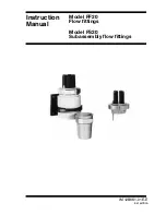
Page 1: ...BEKOMAT 8 BEKOMAT 9 EN English 01 3048 Condensate drain Installation and operating manual ...

Page 2: ...Installation and operating manual EN 2 BEKOMAT 8 9 ...

Page 3: ... 2 1 Type plate 9 2 2 Product overview and description 10 2 3 Function 11 2 3 1 Alarm mode 11 2 4 Dimensions 12 2 4 1 BEKOMAT 8 12 2 4 2 BEKOMAT 9 12 2 5 Technical data 13 2 5 1 Performance data 13 3 Installation 14 3 1 Warning 14 3 2 Installation 15 4 Electrical installation 16 4 1 Installation instructions 16 4 2 Electrical connections 16 5 Operation 18 5 1 Function test 19 6 Maintenance and ser...

Page 4: ...ine parts 1 1 2 On the device Observe installation and operating instructions on type plate 1 2 Signal words according to ISO 3864 and ANSI Z 535 DANGER Imminent danger Consequences of non compliance serious or even fatal injury WARNING Potential danger Consequences of non compliance serious or even fatal injury CAUTION Imminent danger Consequences of non compliance injury and or damage to propert...

Page 5: ...device parts against vibration and impact Perform a leakage test DANGER Mains voltage Risk of serious or even fatal injury from electric shock when coming into contact with non insulated powered components For the electrical installation of the device adhere to all applicable regulations e g VDE 0100 IEC 60364 Before carrying out any maintenance work de energize the system All electrical work must...

Page 6: ...cialist technical personnel must have read this manual A copy of this installation and operating manual must be kept near the device where it is at all times accessible to staff In addition to the instructions in this document always comply with the statutory regulations for machine operation accident prevention and safety This also applies to the use of accessories and spare parts 1 Specialist te...

Page 7: ... authorised and suitably trained technical personnel If you detect any damage do not start the device Always adhere to the specified transport and storage temperatures Protect the device against direct sunlight and heat radiation The device must be stored in the original packaging Seal the packaging and store it in a dry and frost free room Ensure that the storage temperature does not exceed the l...

Page 8: ...l data Do not operate the device with any media fluids gas vapour mixtures other than those listed above Any other use of the device is deemed improper and poses a risk to persons property and the environment 1 6 Warranty and liability All warranty shall be voided if the BEKOMAT is used improperly for a purpose other than the intended or is operated outside the limits specified in the technical da...

Page 9: ...stemp 1 C 60 C Medium Druckluft Kondensat Inhalt 19 5 l Behälternr 12345678 Beispiel Example Designation Description Hersteller BEKO TECHNOLOGIES GmbH Name of manufacturer Baujahr 2016 Year of manufacture zul Betriebsdruck 0 5 10 bar Max permissible operating pressure zul Betriebstemp 1 C 60 C Max permissible operating temperature Medium Compressed air condensate Permissible media Inhalt 19 5 l Ca...

Page 10: ... 5 6 9 10 8 11 1 Condensate inlet 7 Manual drain 2 Venting line 8 Valve LED 3 Control elements electrical control 9 Alarm LED 4 Solenoid valve 10 Power LED 5 Condensate discharge solenoid valve 11 Test button 6 Type plate NOTICE No permanent drainage Do not use the test button for permanent drainage ...

Page 11: ...the condensate fail to drain off the valve is closed after 2 5 seconds and automatically opened again after 2 seconds This procedure is repeated for 1 minute as the control system tries to resolve the problem 2 3 1 Alarm mode The BEKOMAT is continuously monitored by electronic and sensory devices If a fault or malfunction occurs the BEKOMAT is automatically switched to alarm mode e g due to blocke...

Page 12: ... 331 13 0 485 19 1 146 5 5 7 334 5 13 2 150 5 9 G1 i Flansch flange C 50 x 60 3 DIN 1092 1 30 68 3 2 7 Ø 11 Ø 165 Ø 6 5 G i G i 237 9 3 2 4 2 BEKOMAT 9 734 28 9 Ø 325 Ø 12 8 455 17 9 645 25 4 180 7 1 393 5 15 5 150 5 9 G2 i Flansch flange C 50 x 60 3 DIN 1092 1 25 68 3 2 7 Ø 11 Ø 165 Ø 6 5 G i G i 237 9 3 ...

Page 13: ... data BM 08 BM 09 Operating voltage 230 200 110 100 48 24 VAC 10 50 60 Hz 24 VDC see type plate Power consumption 10 VA Recommended wire cross section Ø 5 8 11 mm 3 x 0 75 mm Fuse medium time lag 0 5 A Alarm relay Contact rating P 125 W VA I 0 1 0 5 A U 250 VAC U 12 VDC 2 5 1 Performance data BM 08 BM 09 Betriebsdruck Operating pressure Jahres Nennleistung Condensate discharge capacity Maximalleis...

Page 14: ...ant installation materials and suitable tools that are in proper working order Before pressurising the system check all unit parts and repair them if necessary Open valves slowly to prevent pressure blows during operation Make sure that no persons can be injured or objects can be damaged by condensate or escaping compressed gas Protect the device parts against vibration and impact Perform a leakag...

Page 15: ...alled above the highest possible condensate level Observe the minimum installation heights Installation of BEKOMAT 8 9 Venting line A Lines must be equipped with ball valve Condensate inlet B Pipes 2 DN 50 must be installed with flange and ball valve short inlet pipe Condensate inlet slope 1 No filter in condensate inlet Condensate discharge C Install pipe 1 for BEKOMAT 9 2 Do not feed to a manifo...

Page 16: ...any maintenance work de energize the system All electrical work must be carried out by authorised specialist technical personnel1 1 Specialist technical personnel Specialist technical personnel are persons who due to their professional qualification and knowledge in the field of measuring control and pneumatic technology and their knowledge of the applicable statutory regulations guidelines and st...

Page 17: ...MAX MIN Connecting power cable Push the cable through the cable screw and connect it to terminals L1 N PE Alarm signal line The device is equipped with a floating alarm relay changeover for the transfer of alarm signals in the event of a fault push the cable through the second cable screw and connect it N C COM Contact is made in the event of a fault or power failure fail safe contact N O COM Cont...

Page 18: ...ening time is sensor controlled based on the actual discharge rate After condensate has been discharged BEKOMAT is empty Valve closes No unnecessary compressed air loss Alarm status ALARM Insufficient pressure to open valve Too much condensate being produced see Technical data Inlet or drain pipe blocked or closed Excessive dirt valve blocked Solenoid valve defective see Maintenance Piping frozen ...

Page 19: ...ALARM LED flashes yellow VALVE led is lit Valve to condensate discharge is opened Testing alarm function To test the solenoid valve alarm function close the condensate inlet and press and hold the test button for approx 1 minute Alarm relay switches over Release TEST button BEKOMAT returns to normal mode operation Condensate inlet is again open Min operating pressure 0 5 bar ...

Page 20: ...Function test Press the TEST button Visual inspection daily Maintenance Replace wearing parts kit Perform leakage test Perform function test Check adhesive label and replace if necessary Check valve core length Check cable connections Clean annually Function test We strongly recommend performing a daily function test of the BEKOMAT To test the solenoid valve press the test button briefly for appro...

Page 21: ...d integrated electronic components Never clean the device with a wet cloth Do not use aggressive detergents Do not clean or operate the device with hard or pointed implements Cleaning A Cleaning container Do not actuate the test switch but Close inlet Carefully open manual drain at container Residual pressure flushes container B Cleaning sensor tube Remove the flange at the top of the container lo...

Page 22: ...Gasket kit 8x gaskets for sensor 1x gasket for manual drain BEKOMAT 8 9 2000683 PCB 230 VAC 1x PCB 230 VAC BEKOMAT 8 2000763 BEKOMAT 9 4005381 PBC 110 VAC 1x PCB 110 VAC BEKOMAT 8 2002768 BEKOMAT 9 4013115 PCB 24 VDC 1x PCB 24 VDC BEKOMAT 8 2000231 BEKOMAT 9 2001970 6 4 Accessories Table of available accessories Picture Description Order number Trace heating system BEKOMAT 8 9 2801233 Heater tape ...

Page 23: ...e into contact with a hazardous substance also enclose a declaration of decontamination The relevant templates can be downloaded from our homepage at www beko technologies com If your device arrives at our service workshop without a declaration of decontamination and should our personnel be concerned about any media with which it might have come into contact we will contact you A repair will only ...

Page 24: ...Installation and operating manual EN 24 BEKOMAT 8 9 8 Declaration of Conformity ...

Page 25: ...on Condensate drain for the electronically level controlled discharge of condensate in the compressed air system Pressure Equipment Directive PED 97 23 EC Applied conformity assessment procedure Module A Internal production control Category I Low Voltage Directive 2006 95 EC Applied standards EN 61010 1 2010 Section 1 14 16 17 Annex A D F G I ZA Year of CE labeling 2003 The devices with working vo...

Page 26: ...Installation and operating manual EN 26 BEKOMAT 8 9 ...

Page 27: ...EN Installation and operating manual BEKOMAT 8 9 27 ...

Page 28: ...2 nave 6 E 08758 Cervelló Phone 34 93 632 76 68 info es beko technologies es 中華人民共和國香港特別行政區 Hong Kong SAR of China BEKO TECHNOLOGIES LIMITED Unit 1010 Miramar Tower 132 Nathan Rd Tsim Sha Tsui Kowloon Hong Kong Phone 852 5578 6681 Hong Kong Phone 86 147 1537 0081 China tim chan beko technologies com India BEKO COMPRESSED AIR TECHNOLOGIES Pvt Ltd Plot No 43 1 CIEEP Gandhi Nagar Balanagar Hyderabad ...

Reviews: