background image

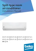
Split-type room  

air conditioner

Installation Manual

BEVPI 090 BEVPI 091 BEVPI 120  BEVPI 121  
BEVPI 180 BEVPI 181  BEVPI 240  BEVPI 241 

EN

SI

Summary of Contents for BEVPI 090

Page 1: ...Split type room air conditioner Installation Manual BEVPI 090 BEVPI 091 BEVPI 120 BEVPI 121 BEVPI 180 BEVPI 181 BEVPI 240 BEVPI 241 EN SI ...

Page 2: ...This product has been produced in environmentally friendly modern facilities Complies with the WEEE Regulation Does not contain PCB C Important information or useful hints about usage A Warning for hazardous situations with regard to life and property This symbol shows that the operation manual should be read carefully This symbol shows that a service personne should be handling this equipment wit...

Page 3: ...Note on pipe length 37 7 2 Connection instructions refrigerant piping 37 7 3 Instructions for connecting piping to indoor unit 41 7 4 Instructions for connecting piping to outdoor unit 42 8 Air evacuation 44 8 1 Preparations and precautions 44 8 2 Evacuation instructions 44 9 Electrical and gas leak checks 48 9 1 Electrical safety checks 48 9 2 Gas leak checks 49 10Test run 50 10 1 Before test run...

Page 4: ... other than the specified refrigerant enter the unit The presence of other gases or substances will lower the unit s capacity and can cause abnormally high pressure in the refrigeration cycle This can cause explosion and injury Do not allow children to play with the air conditioner Children must be supervised around the unit at all times Installationmustbeperformedbyanauthorizeddealerorspecialist ...

Page 5: ...t other appliances to the same outlet Insufficient electrical capacity or defects in electrical work can cause electrical shock or fire For all electrical work use the specified cables Connect cables tightly and clamp them securely to prevent external forces from damaging the terminal Improper electrical connections can overheat and cause fire and may also cause shock Allwiringmustbeproperlyarrang...

Page 6: ...es for example open flames an operating gas appliance or an operating electric heater 2 Do not pierce or burn 3 Appliance shall be stored in a well ventilated area where the room size corresponds to the room area as specific for operation 4 Be aware that refrigerants may not contain an odour C Note Clause 1 to 4 are required for the units adopt R32 R290 Refrigerant Warning Forunitsthathaveanauxili...

Page 7: ...asses 1 Thisair conditioningunitcontainsfluorinatedgasses Forspecificinformationonthetypeofgasandthe amount pleaserefertotherelevantlabelontheunit itself 2 Installation service maintenanceandrepairofthisunit mustbeperformedbyacertifiedtechnician 3 Productuninstallationandrecyclingmustbeperformed byacertifiedtechnician 4 Ifthesystemhasaleak detectionsysteminstalled it mustbecheckedforleaksatleastev...

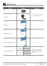
Page 8: ...install the air conditioner Improper installation may result in water leakage electrical shock and fire or cause the equipment to fail Name Shape Quantity Mounting plate 1 Clip anchor 5 Mounting plate fixing screw ST3 9 X 25 5 Remote controller 1 Fixing screw for remote controller holder ST2 9 x 10 2 Optional Parts Remote controller holder 1 Dry battery AAA LR03 2 2 Accessories ...

Page 9: ...in joint User manual Split type room air conditioner User Manual EN 1 Installation manual 1 Remote controller illustration Air conditioner Remote control illustration EN 1 Connect ing pipe assembly Liquid side Ø6 35 1 4in Parts you must purchase Consult the dealer about the pipe size Ø9 52 3 8in Gas side Ø9 52 3 8in Ø12 7 1 2in Ø16 5 8in ...

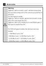
Page 10: ...32 frigerant models Appliance shall be installed operated and stored in a room with a floor area larger than 4m2 Appliance shall not be installed in an unvertilated space if that space is smaller than 4m2 For R290 refrigerant models the minimum room size needed 9000Btu h units 13m2 9000Btu h and 12000Btu h units 17m2 12000Btu h and 18000Btu h units 26m2 18000Btu h and 24000Btu h units 35m2 2 Acces...

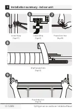
Page 11: ...allation Manual 11 120 EN 12cm 4 75in 15cm 5 9in 12cm 4 75in 2 3m 90 55in Select Installation Location Page 14 Determine Wall Hole Position Page 15 3 Attach Mounting Plate Page 15 Drill Wall Hole Page 16 3 Installation summary indoor unit ...

Page 12: ...it type room air conditioner Installation Manual 5 Connect Piping Page 37 Connect Wiring Page 22 Prepare Drain Hose Page 18 Wrap Piping and Cable Page 25 Mount Indoor Unit Page 26 3 Installation summary indoor unit ...

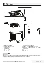
Page 13: ... 4 Signal Cable 5 Refrigerant Piping 6 Remote Holder 7 Remote Control Some Units 8 Outdoor Unit Power Cable Some Units 9 Functional Filter On Front of Main Filter Some Units 10 Louver 11 Front Panel C Note Illustrationsinthismanualareforexplanatorypurposes Theactualshapeofyourindoor unitmaybeslightlydifferent Theactualshapeshallprevail 4 Unit parts ...

Page 14: ...oose an appropriate location for the unit Proper installation locations meet the following standards Good air circulation Convenient drainage Noise from the unit will not disturb other people Firm and solid the location will not vibrate Strong enough to support the weight of the unit A location at least one meter from all other electrical devices e g TV radio computer DO NOT install unit in the fo...

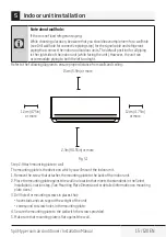
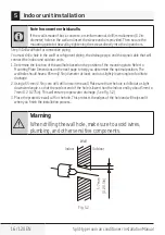
Page 15: ...g 15cm 5 9in or more 12cm 4 75in or more 12cm 4 75in or more 2 3m 90 55in or more Fig 5 1 Step 2 Attach mounting plate to wall The mounting plate is the device on which you will mount the indoor unit 1 Remove the screw that attaches the mounting plate to the back of the indoor unit 2 Place the mounting plate against the wall in a location that meets the standards in the Select Installation Locatio...

Page 16: ... on the position of the mounting plate Refer to Mounting Plate Dimensions on the next page to help you determine the optimal position The wall hole should have a 65mm 2 5in diameter at least and at a slightly lower angle to facilitate drainage 2 Using a 65 mm 2 5in core drill drill a hole in the wall Make sure that the hole is drilled at a slight downward angle so that the outdoor end of the hole ...

Page 17: ... plate Height of indoor unit relative to plate Recommended position of wall hole both to the left and right of mounting plate Relative distances between screw holes Correct orientation of Mounting Plate Indoor unit outline Indoor unit outline Right rear wall hole 65mm 2 5in Right rear wall hole 65mm 2 5in Left rear wall hole 65mm 2 5in 348 4mm 13 7in 426mm 16 8in 101mm 4in 192mm 7 55in 722mm 28 45...

Page 18: ...47mm 1 85in 47mm 1 85in 40mm 1 55in Step 4 Prepare refrigerant piping The refrigerant piping is inside an insulating sleeve attached to the back of the unit You must prepare the piping before passing it through the hole in the wall Refer to the Refrigerant Piping Connection section of this manual for detailed instructions on pipe flaring and flare torque requirements technique etc 1 Based on the p...

Page 19: ...ed piping connect the indoor unit s refrigerant piping to the connective piping that will join the indoor and outdoor units Refer to the Refrigerant Piping Connection section of this manual for detailed instructions 5 Based on the position of the wall hole relative to the mounting plate determine the necessary angle of your piping 6 Grip the refrigerant piping at the base of the bend 7 Slowly with...

Page 20: ... Attach drain hose extension purchased separately to the end of drain hose 3 Wrap the connection point firmly with Teflon tape to ensure a good seal and to prevent leaks 4 For the portion of the drain hose that will remain indoors wrap it with foam pipe insulation to prevent condensation 5 Remove the air filter and pour a small amount of water into the drain pan to make sure that water flows from ...

Page 21: ...ure proper drainage NOT CORRECT Kinks in the drain hose will create water traps NOT CORRECT Kinks in the drain hose will create water traps NOT CORRECT Do not place the end of the drain hose in water or in containers that collect water This will prevent proper drainage Fig 5 5 Fig 5 7 Fig 5 6 Fig 5 8 5 Indoor unit installation ...

Page 22: ...l polesandhasacontactseparationofatleast1 8in 3mm mustbeincorporatedinthe fixedwiring Thequalifiedtechnicianmustuseanapprovedcircuitbreakerorswitch 7 Onlyconnecttheunittoanindividualbranchcircuitoutlet Donotconnectanother appliancetothatoutlet 8 Makesuretoproperlygroundtheairconditioner 9 Everywiremustbefirmlyconnected Loosewiringcancausetheterminaltooverheat resultinginproductmalfunctionandpossib...

Page 23: ... determined by the maximum current of the unit The maximum current is indicated on the nameplate located on the side panel of the unit Refer to this nameplate to choose the right cable fuse or switch Take note of fuse specifications The air conditioner s circuit board PCB is designed with a fuse to provide overcurrent protection The specifications of the fuse are printed on the circuit board such ...

Page 24: ... right side of the unit This will reveal the terminal block Terminal block Wire cover Screw Cable clamp Fig 5 9 The Wiring Diagram is located on the inside of the indoor unit s wire cover A Warning Allwiringmustperformedstrictlyinaccordancewiththe wiringdiagramlocatedontheinsideoftheindoorunits wirecover 4 Unscrew the cable clamp below the terminal block and place it to the side 5 Facing the back ...

Page 25: ...ssing the piping drain hose and the signal cable through the wall hole you must bundle them together to save space protect them and insulate them 1 Bundle the drain hose refrigerant pipes and signal cable according to Fig 5 10 Indoor Unit Space behind unit Refrigerant piping Insulation tape Signal wire Drain hose Fig 5 10 Drain hose must be on bottom Make sure that the drain hose is at the bottom ...

Page 26: ... sealed to prevent dirt or foreign materials from entering the pipes 3 Slowly pass the wrapped bundle of refrigerant pipes drain hose and signal wire through the hole in the wall 4 Hook the top of the indoor unit on the upper hook of the mounting plate 5 Check that unit is hooked firmly on mounting by applying slight pressure to the left and right hand sides of the unit The unit should not jiggle ...

Page 27: ...he bracket or wedge that is propping up the unit 7 Using even pressure push down on the bottom half of the unit Keep pushing down until the unit snaps onto the hooks along the bottom of the mounting plate Unit is adjustable Keep in mind that the hooks on the mounting plate are smaller than the holes on the back of the unit If you find that you don t have ample room to connect embedded pipes to the...

Page 28: ...ds that will help you choose an appropriate location for the unit Proper installation locations meet the following standards Meets all spatial requirements shown in Installation Space Requirements Fig 6 1 Good air circulation and ventilation Firm and solid the location can support the unit and will not vibrate Noise from the unit will not disturb others Protected from prolonged periods of direct s...

Page 29: ...l disturb others Near animals or plants that will be harmed by hot air discharge Near any source of combustible gas In a location that is exposed to large amounts of dust In a location exposed to a excessive amounts of salty air Special considerations for extreme weather If the unit is exposed to heavy wind Install unit so that air outlet fan is at a 90 angle to the direction of the wind If needed...

Page 30: ...uire a drain joint Before bolting the outdoor unit in place you must install the drain joint at the bottom of the unit Note that there are two different types of drain joints depending on the type of outdoor unit If the drain joint comes with a rubber seal see Fig 6 4 A do the following 1 Fit the rubber seal on the end of the drain joint that will connect to the outdoor unit 2 Insert the drain joi...

Page 31: ... A B Base pan hole of outdoor unit Seal Drain joint Seal Fig 6 4 A In cold climates Incoldclimates makesurethatthedrainhoseisasverticalaspossibletoensureswift waterdrainage Ifwaterdrainstooslowly itcanfreezeinthehoseandfloodtheunit Step 3 Anchor outdoor unit The outdoor unit can be anchored to the ground or to a wall mounted bracket Unit mounting dimensions The following is a list of different out...

Page 32: ...1 6 325 12 8 700x550x275 27 5 x21 6 x10 82 450 17 7 260 10 24 770x555x300 30 3 x21 85 x11 81 487 19 2 298 11 73 800x554x333 31 5 x21 8 x13 1 514 20 24 340 13 39 845x702x363 33 25 x27 63 x14 29 540 21 26 350 13 8 900x860x315 35 4 x33 85 x12 4 590 23 2 333 13 1 945x810x395 37 2 x31 9 x15 55 640 25 2 405 15 95 946x810x420 37 21 x31 9 x16 53 673 26 5 403 15 87 946x810x410 37 21 x31 9 x16 14 673 26 5 4...

Page 33: ...theweightoftheunit 1 Mark the position of bracket holes based on dimensions in the Unit Mounting Dimensions chart 2 Pre drill the holes for the expansion bolts 3 Clean dust and debris away from holes 4 Place a washer and nut on the end of each expansion bolt 5 Thread expansion bolts through holes in mounting brackets put mounting brackets in position and hammer expansion bolts into the wall 6 Chec...

Page 34: ...ower to fixed wiring a switch or circuit breaker that disconnects all poles and has a contact separation of at least 1 8in 3mm must be incorporated in the fixed wiring The qualified technician must use an approved circuit breaker or switch 7 Only connect the unit to an individual branch circuit outlet Do not connect another appliance to that outlet 8 Make sure to properly ground the air conditione...

Page 35: ... inside b Strip the insulation from the ends of the wires c Using a wire crimper crimp u lugs on the ends of the wires Pay attention to live wire While crimping wires make sure you clearly distinguish the Live L Wire from other wires A Warning All wiring must performed strictly in accordance with the wiringdirgramlocatedinsidetheoutdoorunitswirecover 2 Unscrew the electrical wiring cover and remov...

Page 36: ... the cable clamp fasten the cable to the unit Screw the cable clamp down tightly 7 Insulate unused wires with PVC electrical tape Arrange them so that they do not touch any electrical or metal parts 8 Replace the wire cover on the side of the unit and screw it in place Cover Outdoor Unit Wiring Diagram is located on the inside of the wire cover on the outdoor unit Fig 6 6 6 Outdoor unit installati...

Page 37: ...ight m R410A inverter split air conditioner 15 000 25 82ft 10 33ft 15 000 and 24 000 30 98 5ft 20 66ft 24 000 and 36 000 50 164ft 25 82ft 36 000 and 60 000 65 213ft 30 98 5ft 7 2 Connection instructions refrigerant piping Step 1 Cut pipes When preparing refrigerant pipes take extra care to cut and flare them properly This will ensure efficient operation and minimize the need for future maintenance...

Page 38: ...t piping connection They must be completely removed 1 Hold the pipe at a downward angle to prevent burrs from falling into the pipe 2 Using a reamer or deburring tool remove all burrs from the cut section of the pipe Pipe Point down Reamer Fig 7 2 Step 3 Flare pipe ends Proper flaring is essential to achieve an airtight seal 1 After removing burrs from cut pipe seal the ends with PVC tape to preve...

Page 39: ...PVC tape from ends of pipe when ready to perform flaring work 5 Clamp flare form on the end of the pipe The end of the pipe must extend beyond the edge of the flare form in accordance with the dimensions shown in the table below Fig 7 4 Piping extension beyond flare form Outer diameter of pipe mm A mm Min Max Ø 6 35 Ø 0 25 0 7 0 0275 1 3 0 05 Ø 9 52 Ø 0 375 1 0 0 04 1 6 0 063 Ø 12 7 Ø 0 5 1 0 0 04...

Page 40: ...e form then inspect the end of the pipe for cracks and even flaring Step 4 Connect pipes When connecting refrigerant pipes be careful not to use excessive torque or to deform the piping in any way You should first connect the low pressure pipe then the high pressure pipe Minimum bend radius When bending connective refrigerant piping the minimum bending radius is 10cm See Fig 7 6 Radius 10cm 4in Fi...

Page 41: ...4 While firmly gripping the nut on the unit tubing use a torque wrench to tighten the flare nut according to the torque values in the Torque Requirements table below Loosen the flaring nut slightly then tighten again Fig 7 8 Torque requirements Outer diameter of pipe mm Tightening torque N cm Add tightening torque N m Ø 6 35 Ø 0 25 1 500 11lb ft 1 600 11 8lb ft Ø 9 52 Ø 0 375 2 500 18 4lb ft 2 600...

Page 42: ...he cover from the packed valve on the side of the outdoor unit See Fig 7 9 Valve cover Fig 7 9 2 Remove protective caps from ends of valves 3 Align flared pipe end with each valve and tighten the flare nut as tightly as possible by hand 4 Using a spanner grip the body of the valve Do not grip the nut that seals the service valve See Fig 7 10 C Usespannertogripmainbodyofvalve Torquefromtighteningth...

Page 43: ...g 7 10 5 While firmly gripping the body of the valve use a torque wrench to tighten the flare nut according to the correct torque values 6 Loosen the flaring nut slightly then tighten again 7 Repeat Steps 3 to 6 for the remaining pipe 7 Refrigerant piping connection ...

Page 44: ... and moisture from the system Evacuation should be performed upon initial installation and when unit is relocated Before performing evacuation Check to make sure that both highpressure and low pressure pipes between the indoor and outdoor units are connected properly in accordance with the Refrigerant Piping Connection section of this manual Check to make sure all wiring is connected properly 8 2 ...

Page 45: ...pound Meter reads 76cmHG 105 Pa 6 Close the Low Pressure side of the manifold gauge and turn off the vacuum pump 7 Wait for 5 minutes then check that there has been no change in system pressure 8 If there is a change in system pressure refer to Gas Leak Check section for information on how to check for leaks If there is no change in system pressure unscrew the cap from the packed valve high pressu...

Page 46: ... further using a torque wrench if needed C Openvalvestemsgently Whenopeningvalvestems turnthehexagonalwrenchuntilithitsagainstthestopper Donottrytoforcethevalvetoopenfurther C Noteonaddingrefrigerant Some systems require additional charging depending on pipe lengths The standard pipe length varies according to local regulations For example in North America the standard pipe length is 7 5m 25 In ot...

Page 47: ...Z ft Inverter R410A Pipe length standard length x 15g m Pipe length standard length x 0 16oZ ft Fixed frequency R410A Pipe length standard length x 20g m Pipe length standard length x 0 21oZ ft Liquid Side Ø 9 52 ø 0 375 R22 Pipe length standard length x 60g m Pipe length standard length x 0 64oZ ft Inverter R410A Pipe length standard length x 30g m Pipe length standard length x 0 32oZ ft Fixed fr...

Page 48: ... be less than 4 Note This may not be required for some locations in the US During test run Check for Electrical Leakage During the Test Run use an electroprobe and multimeter to perform a comprehensive electrical leakage test If electrical leakage is detected turn off the unit immediately and call a licensed electrician to find and resolve the cause of the leakage Note This may not be required for...

Page 49: ...d detergent to all pipe connection points on the indoor unit and outdoor unit The presence of bubbles indicates a leak Leak Detector Method If using leak detector refer to the device s operation manual for proper usage instructions After performing gas leak checks After confirming that the all pipe connection points DO NOT leak replace the valve cover on the outside unit 9 Electrical and gas leak ...

Page 50: ...button on the remote controller to turn it on 3 Press the MODE button to scroll through the following functions one at a time COOL Select lowest possible temperature HEAT Select highest possible temperature 4 Let each function run for 5 minutes and perform the following checks List of checks to perform Pass Fail No electrical leakage Unit is properly grounded All electrical terminals properly cove...

Page 51: ... following a Using remote control return unit to normal operating temperature b Using insulation tape wrap the indoor refrigerant pipe connections that you left uncovered during the indoor unit installation process If ambient temperature is below 17 C 63 F You can t use the remote controller to turn on the COOL function when the ambient temperature is below 17 C In this instance you can use the MA...

Page 52: ...wing options Dispose of the appliance at designated municipal electronic waste collection facility When buying a new appliance the retailer will take back the old appliance free of charge The manufacturer will take back the old appliance free of charge Sell the appliance to certified scrap metal dealers C Specialnotice Disposing of this appliance in the forest or other natural surroundings endange...

Page 53: ...cycling should be carried out by natural persons that hold relevant certificates If the system has a leakage detection system installed leakage checks should be performed at least every 12 months make sure system operate properly If product must be performed leakage checks it should specify Inspection cycle establish and save records of leakage checks C Note For hermetically sealed equipment porta...

Page 54: ... for use with flammable refrigerants i e no sparking adequately sealed or intrinsically safe 5 Presence of fire extinguisher If any hot work is to be conducted on the refrigeration equipment or any associated parts appropriate fire extinguishing equipment shall be available to hand Have a dry power or CO2 fire extinguisher adjacent to the charging area 6 No ignition sources No person carrying out ...

Page 55: ...l components shall include initial safety checks and component inspection procedures If a fault exists that could compromise safety then no electrical supply shall be connected to the circuit until it is satisfactorily dealt with If the fault cannot be corrected immediately but it is necessary to continue operation and adequate temporary solution shall be used This shall be reported to the owner o...

Page 56: ...tinual vibration from sources such as compressors or fans 13 Detection of flammable refrigerants Under no circumstances shall potential sources of ignition be used in the searching for or detection of refrigerant leaks A halide torch or any other detector using a naked flame shall not be used 14 Leak detection methods The following leak detection methods are deemed acceptable for systems containin...

Page 57: ...ork to take place This operation is absolutely vital if brazing operations on the pipe work are to take place Ensure that the outlet for the vacuum pump is not closed to any ignition sources and there is ventilation available 16 Charging procedures In addition to conventional charging procedures the following requirements shall be followed Ensure that contamination of different refrigerants does n...

Page 58: ...der even temporarily j When the cylinders have been filled correctly and the process completed make sure that the cylinders and the equipment are removed from site promptly and all isolation valves on the equipment are closed off k Recovered refrigerant shall not be charged into another refrigeration system unless it has been cleaned and checked 18 Labelling Equipment shall be labelled stating tha...

Page 59: ...ssor oils are to be removed ensure that they have been evacuated to an acceptable level to make certain that flammable refrigerant does not remain within the lubricant The evacuation process shall be carried out prior to returning the compressor to the suppliers Only electric heating to the compressor body shall be employed to accelerate this process When oil is drained from a system it shall be c...

Page 60: ...nih delih teh navodil Ta izdelek je bil izdelan v okolju prijaznih sodobnih objektih Ustreza zahtevam OEEO Ne vsebuje PCB C Pomembne informacije ali uporabni namigi za uporabo A Opozorilo na nevarne situacije ki ogrožajo življenje in lastnino Ta simbol pomeni da morate pozorno prebrati navodila za uporabo Ta simbol pomeni da mora z opremo ravnati servisno osebje z upoštevanjem navodil za namestite...

Page 61: ...ilnega sredstva 95 7 3 Navodila za priključitev cevi na notranjo enoto 99 7 4 Navodila za priključitev cevi na zunanjo enoto 100 8 Izpraznitev zraka 102 8 1 Priprave in previdnostni ukrepi 102 8 2 Navodila za praznjenje 102 9 Preverjanje električne napeljave in preverjanje uhajanja plina 106 9 1 Preverjaje varnosti električne napeljave 106 9 2 Preverjanje uhajanja plina 107 10Preskus delovanja 108...

Page 62: ...sredstvapazite davenotoneprodrejo druge snovi ali plini razen navedenega hladilnega sredstva Prisotnostdrugihplinovalisnovizmanjšazmogljivostenoteinlahko povzroči neobičajno visok tlak v hladilnem ciklu To lahko povzroči eksplozij ali poškodbo Otrokomnedovolite daseigrajosklimatskonapravo Otrokemorate v bližini enote ves čas nadzirati Napravo mora namestiti pooblaščeni prodajalec ali strokovnjak P...

Page 63: ...ujte drugih naprav v isto vtičnico Nezadostna električna zmogljivost ali napake v električni inštalaciji lahko povzročijo električni udar ali požar Za vso električno inštalacijo uporabite navedene kable Kable tesno povežite in jih trdno spnite da preprečite da bi zunanje sile poškodovale terminal Nepravilne električne povezave se lahko pregrejejo ter povzročijo požar in električni udar Vsa elektri...

Page 64: ...ali delujoč električni grelnik 2 Naprave ne luknjajte ali sežigajte 3 Napravo hranite v dobro prezračenem območju kjer velikost prostora ustreza območju prostora ki je navedeno za delovanje 4 Upoštevajte da je hladilno sredstvo lahko brez vonja C Opomba Točke 1 do 4 so zahtevane za enote ki uporabljajo hladilno sredstvo R32 R290 Opozorilo Enot s pomožnim električnim grelnikom ne namestite v območj...

Page 65: ...uoriranih plinov 1 Klimatska naprava vsebuje fluorirane pline Za natančne informacije o vrsti in količini plina si oglejte ustrezno oznako nameščeno na sami enoti 2 Namestitev servisiranje vzdrževanje in popravilo enote mora izvesti certificiran tehnik 3 Izdelek mora odstraniti in reciklirati certificiran tehnik 4 Če je v izdelku nameščen sistem za zaznavanje uhajanja ga morate preveriti za uhajan...

Page 66: ... dodatno opremo Napačna namestitev lahko privede do iztekanja vode električnih udarov in požara ali povzroči okvaro opreme Ime Oblika Količina Montažna plošča 1 Zidni vložek 5 Pritrdilni vijak za montažno ploščo ST3 9 X 25 5 Daljinski upravljalnik 1 Pritrdilni vijak za nosilec daljinskega upravljalnika ST2 9 x 10 2 Izbirni deli Nosilec daljinskega upravljalnika 1 Suha baterija AAA LR03 2 2 Dodatki...

Page 67: ...la za uporabnike Split type room air conditioner User Manual EN 1 Navodila za namestitev 1 Ilustracije daljinskega upravljalnika Air conditioner Remote control illustration EN 1 Sklop priključne cevi Tekočinska stran Ø6 35 1 4 in Deli ki jih morate kupiti Glede velikosti cevi se posvetujte s prodajalcem Ø9 52 3 8 in Plinska stran Ø9 52 3 8 in Ø12 7 1 2 in Ø16 5 8 in ...

Page 68: ...stvom R32 Naprava mora biti nameščena se mora uporabljati in biti shranjena v prostoru s talno površino večjo od 4 m2 Naprava ne sme biti nameščena v neprezračenem prostoru manjšem od 4 m2 Za modele s hladilnim sredstvom R290 je najmanjša zahtevana velikost prostora naslednja Enote 9000 Btu h 13 m2 Enote 9000 Btu h in 12000 Btu h 17 m2 Enote 12000 Btu h in 18000 Btu h 26 m2 Enote 18000 Btu h in 24...

Page 69: ...69 120 SI 12 cm 4 75 in 15 cm 5 9 in 12 cm 4 75 in 2 3 m 90 55 in Izberite mesto za namestitev stran 72 Določite položaj luknje v steni stran 73 3 Namestite montažno ploščo stran 73 Izvrtajte luknjo v steno stran 74 3 Kratek pregled namestitve notranja enota ...

Page 70: ...a Navodila za namestitev 5 Priključite cevi stran 95 Priključite električno napeljavo stran 80 Pripravite cev za odvajanje vode stran 76 Ovijte cevi in kable stran 83 Namestite notranjo enoto stran 84 3 Kratek pregled namestitve notranja enota ...

Page 71: ...dstva 6 Nosilec daljinskega upravljalnika 7 Daljinski upravljalnik pri nekaterih enotah 8 Napajalni kabel zunanje enote pri nekaterih enotah 9 Funkcionalni filter na sprednji strani glavnega filtra pri nekaterih enotah 10 Loputa 11 Sprednja plošča C Opomba Ilustracije v tem priročniku so samo za obrazložitvene namene Dejanska oblika vaše notranje enote se lahko nekoliko razlikuje Pomembna je dejan...

Page 72: ...trezno mesto namestitve za enoto Ustrezna mesta namestitve izpolnjujejo naslednje standarde Dobro kroženje zraka Priročno odvajanje Hrup iz enote ne bo motil drugih oseb Trdno in stabilno mesto namestitve mora biti brez vibracij Dovolj močno da podpira težo enote Mesto ki je najmanj en meter oddaljeno od drugih električnih naprav npr televizorja radia računalnika Enote NE nameščajte na naslednjih ...

Page 73: ... 15 cm 5 9 in ali več 12 cm 4 75 in ali več 12 cm 4 75 in ali več 2 3 m 90 55 in ali več Skica 5 1 2 korak Namestite montažno ploščo na steno Montažna plošča je pripomoček na katerega namestite notranjo enoto 1 Odstranite vijak s katerim je montažna plošča pritrjena na zadnjo stran notranje enote 2 Montažno ploščo položite ob steno na mestu ki izpolnjuje standarde v koraku Izberite mesto za namest...

Page 74: ...ložaj montažne plošče Za pomoč pri določitvi optimalnega položaja glejte razdelek Dimenzije montažne plošče na naslednji strani Luknja v steni mora imeti premer najmanj 65 mm 2 5 palca in nekoliko nižji kot za lažje odvajanje vode 2 Izvrtajte luknjo v steno s kronskim vrtalnikom premera 65 mm 2 5 palca Luknjo morate izvrtati pod kotom nekoliko navzdol tako da je zunanji del luknje nižje od notranj...

Page 75: ...o Priporočeni položaj luknje v steni levo in desno od montažne plošče Relativne razdalje med luknjami za vijake Pravilna usmerjenost montažne plošče Obris notranje enote Obris notranje enote Izvrtina v steni na desni strani zadaj 65 mm 2 5 in Izvrtina v steni na desni strani zadaj 65 mm 2 5 in Izvrtina v steni na levi strani zadaj 65 mm 2 5 in 348 4 mm 13 7 in 426 mm 16 8 in 101 mm 4 in 192 mm 7 5...

Page 76: ...52 mm 2 05 in 58 mm 2 3 in 319 mm 12 55 in 335 mm 13 2 in 362 mm 14 25 in 57 mm 2 25 in 47 mm 1 85 in 47 mm 1 85 in 40 mm 1 55 in 4 korak Pripravite cev hladilnega sredstva Cev hladilnega sredstva se nahaja v izolacijskem rokavu nameščenem na zadnji strani enote Cev morate pripraviti preden jo napeljete skozi luknjo v steni Glejte razdelek Povezava cevi hladilnega sredstva v tem priročniku za podr...

Page 77: ...e Če cev ni vgrajena priključite cev hladilnega sredstva notranje enote na povezovalno cev s čimer boste povezali notranjo in zunanjo enoto Za podrobna navodila glejte razdelek Povezava cevi hladilnega sredstva 5 Na podlagi položaja luknje v steni glede na montažno ploščo določite potreben kot za cevi 6 Cev hladilnega sredstva primite na jedru upogiba 7 Cev počasi in z enakomernim pritiskom upogni...

Page 78: ...tite podaljšek cevi na voljo ločeno 3 Priključnotočkotrdnoovijtesteflonskimtrakom dazagotovitedobrotesnjenjeinpreprečiteiztekanja 4 Del cevi za odvajanje ki bo ostal v notranjih prostorih ovijte s penasto izolacijo za cevi da preprečite kondenzacijo 5 Odstranite filter za zrak in zlijte malo količino vode v posodo za odvajanje da se prepričate da voda nemoteno izteka iz enote C Opomba glede postav...

Page 79: ...strezno odvajanje vode NAPAČNO Upogibanje cevi za odvajanje vode povzroči vodne pasti NAPAČNO Upogibanje cevi za odvajanje vode povzroči vodne pasti NAPAČNO Konca cevi za odvajanje vode ne postavite v vodo ali v posodo za zbiranje vode S tem bi preprečili pravilno odvajanje vode Skica 5 5 Skica 5 7 Skica 5 6 Skica 5 8 5 Montaža notranje enote ...

Page 80: ... ki zagotavlja izklop napajanja na vseh polih in ima med kontakti razmik vsaj 1 8 palca 3 mm Odobren odklopnik ali stikalo mora uporabljati usposobljen tehnik 7 Enoto priključite samo na ločeno vtičnico odcepnega tokokroga V tisto vtičnico ne priključujte drugih naprav 8 Klimatsko napravo morate ustrezno ozemljiti 9 Vsaka žica mora biti trdno povezana Ohlapno ožičenje lahko povzroči pregrevanje te...

Page 81: ...varovalke ali stikala si oglejte napisno ploščico Upoštevajte specifikacije varovalke Ploščatiskanegavezja PCB klimatskenapravejeopremljenazvarovalkozaprenapetostnozaščito Specifikacijevarovalkesonavedenenaploščitiskanegavezja mednjimi T3 15A 250VAC T5A 250VACitd Notranja enota T5A 250VAC Zunanja enota velja samo za enote ki uporabljajo hladilno sredstvo R32 ali R290 T20A 250VAC 18000Btu h enot T3...

Page 82: ...a biti izvedeno strogo v skladu z diagramom ožičenja ki se nahaja na notranji strani pokrova za žice na notranji enoti 4 Odvijte kabelsko spojko pod priključnim blokom in jo postavite ob stran 5 Ko ste obrnjeni proti zadnji strani enote odstranite plastično ploščo na spodnji levi strani 6 Skozi to režo napeljite signalni kabel z zadnje strani enote proti sprednji 7 Ko ste obrnjeni proti sprednji s...

Page 83: ...skladu s skico 5 10 Notranja enota Prostor za enoto Cev hladilnega sredstva Izolacijski trak Signalni kabel cev za odtekanje vode Skica 5 10 Cev za odvajanje vode mora biti spodaj Cev za odvajanje mora biti v snopu spodaj Če postavite cev za odvajanje vode v snopu zgoraj lahko pride do prevelikega pretoka v posodo za odvajanje kar lahko povzroči požar ali škodo na vodah Signalnega kabla ne preplet...

Page 84: ...ode in signalnega kabla skozi izvrtino v steni 4 Obesite zgornji del notranje enote na zgornji kavelj montažne plošče 5 Prepričajte se da je enota trdno nameščena na montažni plošči tako da jo narahlo potisnete navzdol na levi in desni strani enote Enota se ne sme zibati ali premikati 6 Z enakomernim pritiskom potiskaje navzdol spodnjo polovico enote Enoto potiskajte navzdol dokler se ne zaskoči n...

Page 85: ...čno točko z izolacijskim trakom 6 Odstranite nosilec ali zagozdo ki podpira enoto 7 Z enakomernim pritiskom potiskaje navzdol spodnjo polovico enote Enoto potiskajte navzdol dokler se ne zaskoči na kavlje ob dnu montažne plošče Enota je prilagodljiva Kavlji na montažni plošči so manjši kot luknje na zadnji strani enote Če nimate dovolj prostora za priključitev vgrajenih cevi na notranjo enoto lahk...

Page 86: ...pomočjo katerih boste izbrali ustrezno mesto namestitve za enoto Ustrezna mesta namestitve izpolnjujejo naslednje standarde Izpolnjuje prostorske zahteve prikazane v prostorskih zahtevah za namestitev skica 6 1 Dobro kroženje zraka in prezračenost Trdno in stabilno mesto namestitve mora podpirati enoto in biti brez vibracij Hrup iz enote ne bo motil drugih oseb Zaščiteno pred daljšimi obdobji nepo...

Page 87: ...i ali kjer bi hrup iz enote motil druge osebe V bližini živali ali rastlin ki bi jih lahko poškodoval izpust vročega zraka V bližini virov vnetljivih plinov Na mestih izpostavljenih večjim količinam prahu Na mestih izpostavljenih večji količini slanega zraka Kaj morate upoštevati pri skrajnih vremenskih pogojih Če je enota izpostavljena močnemu vetru Enoto namestite tako da je izhodni ventilator z...

Page 88: ...h s toplotno črpalko potrebujete odtočni spoj Preden zunanjo enoto privijete na mesto morate na njeni spodnji strani namestiti odtočni spoj Na voljo sta dve različni vrsti odtočnih spojev odvisno od vrste zunanje enote Če je odtočni spoj opremljen z gumijastim tesnilom glejte skico 6 4 A storite naslednje 1 Namestite gumijasto tesnilo na koncu odtočnega spoja ki bo priključen na zunanjo enoto 2 Vs...

Page 89: ...ji enoti Tesnilo Odtočni spoj Tesnilo Skica 6 4 A V hladnih podnebnih območjih V hladnih podnebnih območjih mora biti cev za odvajanje vode postavljena čim bolj navpično da zagotovite hitro odvajanje vode Če se voda odvaja prepočasi lahko zamrzne v cevi in poplavi enoto 3 korak Pritrdite zunanjo enoto Zunanjo enoto lahko pritrdite na tla ali stenski nosilec Dimenzije za namestitev enote V nadaljev...

Page 90: ...310 31 9x22x12 2 549 21 6 325 12 8 700x550x275 27 5x21 6x10 82 450 17 7 260 10 24 770x555x300 30 3x21 85x11 81 487 19 2 298 11 73 800x554x333 31 5x21 8x13 1 514 20 24 340 13 39 845x702x363 33 25x27 63x14 29 540 21 26 350 13 8 900x860x315 35 4x33 85x12 4 590 23 2 333 13 1 945x810x395 37 2x31 9x15 55 640 25 2 405 15 95 946x810x420 37 21x31 9x16 53 673 26 5 403 15 87 946x810x410 37 21x31 9x16 14 673 ...

Page 91: ...ikratno težo teže enote 1 Označite položaj izvrtin za nosilec na podlagi dimenzij v tabeli z dimenzijami za namestitev enote 2 Vnaprej izvrtajte luknje za raztezne vijake 3 Očistite prah in ostanke stran od izvrtin 4 Namestite podložke in matice na koncih posameznih razteznih vijakov 5 Vstavite raztezne vijake skozi luknje na montažnih nosilcih namestite montažne nosilce in s kladivom zabijte razt...

Page 92: ...a fiksno ožičenje morate vanj vključiti stikalo ali odklopnik ki zagotavlja izklop napajanja na vseh polih in ima med kontakti razmik vsaj 1 8 palca 3 mm Odobren odklopnik ali stikalo mora uporabljati usposobljen tehnik 7 Enoto priključite samo na ločeno vtičnico odcepnega tokokroga V tisto vtičnico ne priključujte drugih naprav 8 Klimatsko napravo morate ustrezno ozemljiti 9 Vsaka žica mora biti ...

Page 93: ...ščami za snemanje izolacije kablov odstranite gumijasti ovoj z obeh koncev kabla da razkrijete približno 40 mm 1 57 palca žic v kablu b Odstranite izolacijo s koncev žic c S kleščami za stiskanje žic stisnite ušesa v obliki črke U na konce žic Bodite pozorni na žice pod napetostjo Med stiskanjem žic morate jasno razlikovati med žico pod napetostjo L in drugimi žicami A Opozorilo Vsoožičenjemorabit...

Page 94: ...5 Potem ko preverite ali so vse povezave trdne z žicami naredite zanko da preprečite da bi v terminal tekla deževnica 6 Pritrdite kabel na enoto s kabelsko spojko Kabelsko spojko trdno privijte 7 Izolirajte neuporabljene žice z električnim trakom iz PVC Razporedite jih tako da se ne dotikajo nobenih električnih ali kovinskih delov 8 Znova namestite pokrov za žice na stran enote in jo privijte na m...

Page 95: ...lna klimatska naprava s pretvornikom R410A 15 000 25 82 ft 10 33 ft 15 000 in 24 000 30 98 5 ft 20 66 ft 24 000 in 36 000 50 164 ft 25 82 ft 36 000 in 60 000 65 213 ft 30 98 5 ft 7 2 Navodila za povezavo cev hladilnega sredstva 1 korak Odrežite cevi Pri pripravi cevi hladilnega sredstva bodite posebej pozorni da jih ustrezno odrežete in robite S tem boste zagotovili učinkovito delovanje in zmanjša...

Page 96: ...t povezave cevi hladilnega sredstva Zato morajo biti popolnoma odstranjene 1 Cev držite pod kotom navzdol da preprečite da bi vanjo padale iglice 2 Z orodjem za posnemanje robov ali orodjem za raziglevanje odstranite vse iglice z odrezanega dela cevi Cev Obrnjeno navzdol Orodje za posnemanje robov Skica 7 2 3 korak Robljenje koncev cevi Ustrezno robljenje je ključnega pomena za doseganje nepredušn...

Page 97: ...akrena cev Skica 7 3 4 Ko ste pripravljeni na izvajanje robljenja odstranite PVC trak s koncev cevi 5 Spnite model za robljenje na koncu cevi Konec cevi mora segati preko roba modela za robljenje v skladu z dimenzijami prikazanimi v spodnji tabeli Skica 7 4 Podaljšanje cevi preko modela za robljenje Zunanji premer cevi mm A mm Min Maks Ø 6 35 Ø 0 25 0 7 0 0275 1 3 0 05 Ø 9 52 Ø 0 375 1 0 0 04 1 6 ...

Page 98: ...el za robljenje nato pa preglejte konec cevi če so na njem razpoke in če je enakomerno zarobljen 4 korak Priključite cevi Ob priključitvi cevi hladilnega sredstva ne uporabite prevelikega navora in pazite da ne deformirate cevi Najprej morate priključiti nizkotlačno cev nato pa visokotlačno cev Minimalni upogibni polmer Minimalniupogibnipolmerpriupogibanjupovezovalnecevihladilnegasredstvaje10cm Gl...

Page 99: ...no držite matico na cevi enote z navornim ključem privijte matico z zarobkom v skladu z vrednostmi navora v spodnji tabeli Zahteve glede navora Matico z zarobkom rahlo odvijte nato pa jo znova privijte Skica 7 8 Zahteve glede navora Zunanji premer cevi mm Navor privitja N cm Dodatni navor privitja N m Ø 6 35 Ø 0 25 1 500 11 lb ft 1 600 11 8 lb ft Ø 9 52 Ø 0 375 2 500 18 4 lb ft 2 600 19 18 lb ft Ø...

Page 100: ...1 Odvijte pokrov z zapornega ventila na strani zunanje enote Glejte skico 7 9 Pokrov ventila Skica 7 9 2 Odstranite zaščitne pokrove s koncev ventilov 3 Poravnajte konec zarobljene cevi s posameznim ventilom in matico z zarobkom trdno privijte z roko 4 S ključem primite ohišje ventila Ne primite matice ki tesni servisni ventil Glejte skico 7 10 C Glavno ohišje ventila primite s ključem Navor zarad...

Page 101: ... Skica 7 10 5 Ko trdno držite ohišje ventila z navornim ključem privijte matico z zarobkom v skladu z ustreznimi vrednostmi navora 6 Matico z zarobkom rahlo odvijte nato pa jo znova privijte 7 Ponovite korake 3 do 6 za preostalo cev 7 Povezava cevi hladilnega sredstva ...

Page 102: ...stranite morebitne pline ki ne kondenzirajo in vlago Praznjenje mora biti izvedeno ob prvotni namestitvi in ob prestavitvi enote Pred praznjenjem Prepričajte se da sta visokotlačna in nizkotlačna cev med notranjo in zunanjo enoto pravilno povezani v skladu z razdelkom Povezava cevi hladilnega sredstva v tem priročniku Prepričajte se da je vsa električna napeljava pravilno povezana 8 2 Navodila za ...

Page 103: ...okler na merilniku zmesi ni prikazana vrednost 76 cmHG 105 Pa 6 Zaprite nizkotlačno stran razdelilnega ventila in izklopite vakuumsko črpalko 7 Počakajte 5 minut in se nato prepričajte da se tlak v sistemu ni spremenil 8 Če se je tlak v sistemu spremenil si oglejte razdelek o preverjanju uhajanja plina za informacije o preverjanju uhajanj Če se tlak v sistemu ni spremenil odvijte pokrov z zaporneg...

Page 104: ...ornim ključem C Steblo ventila nežno odprite Pri odpiranju stebel ventilov vrtite šesterokotni ključ dokler ne dosežete omejilca Ventila ne poskušajte odpirati naprej C Opomba glede dodajanja hladilnega sredstva Pri nekaterih sistemih je potrebno dodatno polnjenje odvisno od dolžine cevi Standardna dolžina cevi se razlikuje glede na lokalne predpise V Severni Ameriki je na primer standardna dolžin...

Page 105: ...etvornik R410A dolžina cevi standardna dolžina x 15 g m dolžinacevi standardnadolžina x0 16oZ ft S fiksno frekvenco R410A dolžina cevi standardna dolžina x 20 g m dolžinacevi standardnadolžina x0 21oZ ft Tekočinska stran Ø 9 52 ø 0 375 R22 dolžina cevi standardna dolžina x 60 g m dolžinacevi standardnadolžina x0 64oZ ft Pretvornik R410A dolžina cevi standardna dolžina x 30 g m dolžinacevi standard...

Page 106: ...apravo za preizkus ozemljitvenega upora Ozemljitveni upor mora biti manjši kot 4 Opomba To morda ni zahtevano za nekatere lokacije v ZDA Med preskusom delovanja Preverjanje električnega uhajanja Med preskusom delovanja s senzorjem napetosti in multimetrom izvedite temeljito preverjanje električnega uhajanja Če je zaznano električno uhajanje nemudoma izklopite enoto in pokličite licenciranega elekt...

Page 107: ...in z milom in vodo Z mehko ščetko nanesite milnico ali tekoči detergent na vse priključne točke cevi na notranji in zunanji enoti Če se pojavijo mehurčki to pomeni uhajanje Način z detektorjem uhajanja V primeru uporabe detektorja uhajanja si oglejte navodila za uporabo naprave za navodila o pravilni uporabi Po preverjanju uhajanja plina Ko ste potrdili da na vseh priključnih točkah cevi NI zaznat...

Page 108: ...a vklopite enoto 3 Pritisnite gumb MODE Način za pomikanje po naslednjih funkcijah eno po eno COOL Hlajenje izberite najnižjo možno temperaturo HEAT Ogrevanje izberite najvišjo možno temperaturo 4 Vsaka funkcija naj deluje 5 minut pri čemer opravite naslednja preverjanja Seznam preverjanj ki jih opravite Uspešno neuspešno Ni električnega uhajanja Enota je pravilno ozemljena Vsi električni priključ...

Page 109: ...to z daljinskim upravljalnikom preklopite nazaj na običajno delovno temperaturo b Notranje povezave cevi hladilnega sredstva ki ste jih med postopkom namestitve notranje enote pustili odkrite ovijte z izolacijskim trakom Če je temperatura okolice nižja od 17 C 63 F Če je temperatura okolice nižja od 17 C z daljinskim upravljalnikom ne morete vklopiti funkcije COOL Hlajenje V tem primeru lahko funk...

Page 110: ...e na voljo naslednje možnosti Napravo zavrzite v namenskem komunalnem obratu za zbiranje odpadne elektronske opreme Ob nakupu nove naprave bo prodajalec brezplačno prevzel staro napravo Staro napravo bo brezplačno prevzel proizvajalec Napravo prodajte certifciranemu prodajalcu odpadne kovine C Posebno obvestilo Če napravo zavržete v gozdu ali drugem naravnem okolju to ogroža vaše zdravje in škoduj...

Page 111: ...me in recikliranje naj izvajajo osebe ki imajo pripadajoča potrdila Če ima sistem nameščen sistem za zaznavanje uhajanja izvajajte preverjanje uhajanja vsaj vsakih 12 mesecev da se prepričate da sistem pravilno deluje V primeru izvajanja preverjanja uhajanja zabeležite cikel preverjanja ter določite in shranite zapise o preverjanju uhajanja C Opomba Preverjanje uhajanja ni potrebno za hermetično z...

Page 112: ...5 Prisotnost gasilnega aparata Če bodo dela izvajana na opremi s hladilnim sredstvom ali katerih koli povezanih delih mora biti na dosegu roke pripravljena ustrezna gasilna oprema V bližini polnilnega območja naj bo pripravljen gasilni aparat s suhim prahom ali gasilni aparat s CO2 6 Brez virov vžiga Nobena oseba ki izvaja delo v zvezi s hladilnim sistemom ki vključuje izpostavljanje katerih koli ...

Page 113: ...ozila varnost ne smete priključiti električnega napajanja na tokokrog dokler napake ne odpravite Če napake ne morete takoj odpraviti vendar pa potrebujete delovanje naprave morate uporabiti ustrezno začasno rešitev To morate sporočiti lastniku opreme tako da so o tem obveščene vse udeležene osebe Začetni varnostni pregledi vključujejo sledeče preverjanje ali so kondenzatorji izpraznjeni to morate ...

Page 114: ... Zaznavanje vnetljivega hladilnega sredstva V nobenih okoliščinah ne smete pri iskanju ali odkrivanju uhajanja hladilnega sredstva uporabiti potencialnih virov vžiga Ne uporabljajte halogenidnega gorilnika ali nobenega drugega detektorja ki uporablja odprt plamen 14 Način zaznavanja uhajanja Za sisteme ki vsebujejo vnetljivo hladilno sredstvo so sprejemljivi naslednji načini zaznavanja uhajanja Za...

Page 115: ...ikom brez kisika morate sistem spustiti na atmosferski tlak da omogočite izvajanje dela Ta postopek je skrajno pomemben če boste na ceveh izvajali spajkanje Prepričajte se da izhod za vakuumsko črpalko ni zaprt za vire vžiga in da je na voljo prezračevanje 16 Postopki polnjenja Poleg običajnih postopkov polnjenja morate upoštevati naslednje zahteve Ob uporabi opreme za polnjenje poskrbite da ne pr...

Page 116: ...enega delovnega tlaka jeklenke niti samo začasno j Ko so jeklenke ustrezno napolnjene in je postopek končan morate jeklenke in opremo takoj odstraniti z lokacije in zapreti vse izolacijske ventile na opremi k Zbranega hladilnega sredstva ne smete polniti v drug hladilni sistem če ni bilo očiščeno in preverjeno 18 Označevanje Opremo morate opremiti z oznako da je bila razgrajena in je iz nje odstra...

Page 117: ...a zbiranje in zlasti ne v jeklenkah Ob odstranjevanju kompresorjev ali kompresorskih olj se prepričate da je izpraznjeno do sprejemljive ravni da zagotovite da vnetljivo hladilno sredstvo ne ostane v mazivu Postopek izpraznitve morate izvesti pred vrnitvijo kompresorja dobavitelju Za pospešitev tega postopka lahko uporabite samo električno ogrevanje ohišja kompresorja Odstranjevanje olja iz sistem...

Page 118: ......

Page 119: ......

Page 120: ...www beko com ...

Page 121: ...Air conditioner remote control User Manual EN ...

Page 122: ...using the product and keep it as a reference for future use Ifyouhandovertheproducttosomeoneelse givetheusermanualaswell Follow all warnings and information in the user manual Meanings of the symbols Following symbols are used in the various section of this manual C Important information or useful hints about usage A Warning for hazardous situations with regard to life and property This product ha...

Page 123: ...dling the remote control 7 3 1 Inserting and replacing batteries 7 4 Remote LED screen indicators 9 5 How to use the basic functions 10 5 1 Auto operation 10 5 2 Cool operation 11 5 3 Dry operation dehumidifying 12 5 4 Fan operation 13 5 5 Heat operation 14 5 6 Setting the timer function 15 6 How to use the advanced functions 20 ...

Page 124: ...ing Function in 24 hours 3 Indoor Setting Temperature Range 17 C 30 C 4 Full function of LCD Liquid Crystal Display C Note Buttons design might be slightly different from the actual one you purchased depending on individual models All the functions described are accomplished by the indoor unit If the indoor unit has no this feature there is no corresponding operation happened when press the relati...

Page 125: ...How to use the basic functions section of this manual 1 2 3 4 6 5 8 9 11 10 12 13 7 On Off Temp Short Cut Mode Fan LED Swing Sleep Turbo Self Clean Zone Follow Timer On Timer Off Model RG57K7 B BGEF 1 Temp Increases temperate in 1 C increments Max temperature is 30 C Temp Decreases temperate in 1 C increments Min temperature is 17 C 2 Short cut Sets and activates your favourite pre settings 3 Time...

Page 126: ...ff 8 Self clean Starts and stops self clean feature 9 Turbo Enables unit to reach preset temperature in shortest possible time 10 Sleep Saves energy during sleeping hours 11 Fan speed Selects fan speeds in the following order Auto Low Med High 12 Mode Scrolls through operation modes as follows Auto Cool Dry Heat Fan C Note PleasedonotselectHeatmodeifthemachineyoupurchasediscoolingonlytype Heat mod...

Page 127: ...e control before use 1 Slide the back cover from the remote control downward exposing the battery compartment 2 Insert the batteries paying attention to match up the and ends of the batteries with the symbols inside the battery compartment 3 Slide the battery cover back into place C Battery notes For optimum product performance Do not mix old and new batteries or batteries of different types Do no...

Page 128: ...8 24 EN Air conditioner remote control User Manual 3 Handling the remote control ...

Page 129: ...splay Displays when Sleep function is activated 7 Zone follow display IndicatesthattheZoneFollowfunctionison 8 Silent display Not available for this unit 9 Temperature Timer display Displays the set temperature by default or timer setting when using Timer On Off functions Temperature range 17 30 C Timer setting range 0 24 hours This display is blank when operating in Fan mode 10 Fan speed display ...

Page 130: ...30 C You can increase or decrease the set temperature in 1 C increments 5 1 Auto operation In Auto mode the unit will automatically select the Cool Fan Heat or Dry mode based on the set temperature 1 Press the Mode button to select Auto mode 2 Set your desired temperature using the Temp or Temp button 3 Press the On Off button to start the unit C Note Fan Speed can t be set in Auto mode 5 How to u...

Page 131: ...ode Fan LED Swing Sleep Turbo Self Clean Timer On Short Cut Timer Off Zone Follow 5 2 Cool operation 1 Press the Mode button to select Cool mode 2 Set your desired temperature using the Temp or Temp button 3 Press the Fan button to select the Fan Speed Auto Low Med or High 4 Press the On Off button to start the unit ...

Page 132: ... Clean Timer On Short Cut Timer Off Zone Follow 5 3 Dry operation dehumidifying 1 Press the Mode button to select Dry mode 2 Set your desired temperature using the Temp or Temp button 3 Press the On Off button to start the unit C Note Fan Speed can t be changed in Dry mode 5 How to use the basic functions ...

Page 133: ...Timer Off Zone Follow 5 4 Fan operation 1 Press the Mode button to select Fan mode 2 Press Fan button to select the Fan Speed Auto Low Med or High 3 Press the On Off button to start the unit C Note You can t set temperature in Fan mode As a result your remote control s LCD screen will not display temperature 5 How to use the basic functions ...

Page 134: ...ct Heat mode 2 Set your desired temperature using the Temp or Temp button 3 Press the Fan button to select the Fan Speed Auto Low Med or High 4 Press the On Off button to start the unit C Note Asoutdoortemperaturedrops theperformanceofyourunit sHeatfunctionmay be affected In such instances we recommend using this air conditioner in conjunction with other heating appliance 5 How to use the basic fu...

Page 135: ...ast time period that you set and an h indicating hours will appear on the display C Note This number indicates the amount of time after the current time that you want the unit to turn on For example if you set Timer On for 2 hours 2 0 h will appear on the screen and the unit will turn on after 2 hours 2 Press the Timer On button repeatedly to set the time when you want the unit to turn on 3 Wait 2...

Page 136: ...rrent time that you want the unit to turn off For example if you set Timer Off for 2 hours 2 0 h will appear on the screen and the unit will turn off after 2 hours 2 Press the Timer Off button repeatedly to set the time when you want the unit to turn off 3 Wait 2 seconds then the Timer Off function will be activated The digital display on your remote control will then return to the temperature dis...

Page 137: ...ch press After 10 hours and up to 24 it will increase in 1 hour increments The timer will revert to zero after 24 hours You can turn off either function by setting its timer to 0 0h Timer On On Off Temp Mode Fan LED Swing Sleep Turbo Self Clean Timer On Short Cut Timer Off Zone Follow Continue to press Timer On or Timer Off until desired time is reached 5 How to use the basic functions ...

Page 138: ... current time For example say that the current time is 1 00 PM and you want the unit to turn on automatically at 7 00 PM You want it to operate for 2 hours then automatically turn off at 9 00 PM Do the following ON OFF ON OFF MODE MODE SHORT SHORT CUT CUT TIMER ON TIMER ON TE MP TE MP 4 8 3 7 Timer Off X12 X16 Timer Off 2 6 Timer On Timer On 1 5 3 sec 3 sec 5 How to use the basic functions ...

Page 139: ...rs then turn off see the figure below Timer On Timer Off Your remote display 6 hours later 8 hours later Timer starts Unit turns On Current time 1PM 2PM 3PM 4PM 5PM 6PM 7PM 8PM 9PM Unit turns Off Timer is set to turn ON 6 hours from current time Timer is set to turn OFF 8 hours from current time 5 How to use the basic functions ...

Page 140: ...on Airborne bacteria can grow in the moisture that condenses around heat exchangers in the unit With regular use most of this moisture is evaporated from the unit By pressing the Self Clean button your unit will clean itself automatically The cleaning cycle takes 30 minutes after which the unit will turn off automatically Pressing the Self Clean button mid cycle will cancel the operation and turn ...

Page 141: ...bles the remote control to measure the temperature at its current location When using Auto Cool or Heat functions measuring ambient temperature from the remote control instead of from the indoor unit itself will enable the air conditioner to optimize the temperature around you and ensure maximum comfort 1 Press Zone Follow button to activate function The remote control will send temperature signal...

Page 142: ......

Page 143: ......

Page 144: ...www beko com ...

Page 145: ......

Page 146: ...uporabnike in druge priložene dokumente ter jih shranite za kasnejšo uporabo Če izdelek predate nekomu drugemu priložite tudi navodila za uporabo Sledite vsem opozorilom in informacijam v navodilih za uporabnike Pomen simbolov Sledeči znaki so uporabljeni v različnih delih teh navodil C Pomembne informacije ali uporabni namigi za uporabo A Opozorilo na nevarne situacije ki ogrožajo življenje in la...

Page 147: ...skim upravljalnikom 7 3 1 Vstavljanje in zamenjava baterij 7 4 Kazalniki LCD zaslona daljinskega upravljalnika 9 5 Uporaba osnovnih funkcij 10 5 1 Delovanje AUTO samodejno 10 5 2 Delovanje COOL hlajenje 11 5 3 Delovanje DRY suho razvlaževanje 12 5 4 Delovanje FAN ventilator 13 5 5 Delovanje HEAT gretje 14 5 6 Nastavitev funkcije TIMER časovnik 15 6 Uporaba naprednih funkcij 20 ...

Page 148: ...rez hlajenja in FAN ventilator 2 Funkcija nastavitve časovnika v 24 urah 3 Razpon nastavitve notranje temperature 17 C 30 C 4 Polna funkcija LCD Liquid Crystal Display C OPOMBA Zasnova gumbov se lahko malo razlikuje od kupljenega daljinskega upravljalnika odvisno od posameznih modelov Vse opisane funkcije doseže notranja enota Če notranja enota nima te funkcije ob pritisku ustreznega gumba na dalj...

Page 149: ...oraba osnovnih funkcij tega priročnika 1 2 3 4 6 5 8 9 11 10 12 13 7 On Off Temp Short Cut Mode Fan LED Swing Sleep Turbo Self Clean Zone Follow Timer On Timer Off Model RG57K7 B BGEF 1 TEMP Poviša temperaturo v korakih po 1 C Najvišja temperatura je 30 C TEMP Zniža temperaturo v korakih po 1 C Najnižja temperatura je 17 C 2 SHORT CUT BLIŽNJICA Nastavi in aktivira vaše priljubljene prednastavitve ...

Page 150: ... čiščenja 9 TURBO Omogoča enoti da doseže predhodno nastavljeno temperaturo v najkrajšem možnem času 10 SLEEP MIROVANJE Prihrani energijo medtem ko spite 11 FAN SPEED HITROST VENTILATORJA Izbere hitrosti ventilatorja v naslednjem vrstnem redu AUTO SAMODEJNO LOW NIZKA MED SREDNJA HIGH VISOKA 12 MODE NAČIN Pomikanje med načini delovanja kot sledi AUTO SAMODEJNO COOL HLAJENJE DRY SUHO HEAT GRETJE FAN...

Page 151: ...adnji pokrov daljinskega upravljalnika navzdol in odkrijte predel z baterijami 2 Vstavite baterije pri tem pa pazite da se konca in baterij ujemata s simboli znotraj predela za baterije 3 Zdrsnite pokrov predela za baterije nazaj na mesto C OPOMBE GLEDE BATERIJ Za optimalno delovanje izdelka Ne mešajte starih in novih baterij ali baterij različnega tipa Ne puščajte baterij v daljinskem upravljalni...

Page 152: ...8 24 SI Pretvornik Klimatska Naprava Slika daljinskega Uporabniški priročnik 3 Ravnanje z daljinskim upravljalnikom ...

Page 153: ...FOLLOW dejanska temperatura Označuje da je funkcija ZONE FOLLOW vklopljena 8 Ugasni zaslon Ni na voljo pri tej enoti 9 Zaslon temperature časovnika Prikažeprivzetonastavljenotemperaturoali nastavitevčasovnika kostavuporabifunkciji TIMERON OFF vklop izklopčasovnika Razpon temperature 17 30 C Razpon nastavitve časovnika 0 24 ur Ta zaslon je prazen ko enota deluje v načinu FAN ventilator 10 Zaslon FA...

Page 154: ... povišate ali znižate po korakih za 1 C 5 1 Delovanje AUTO samodejno V načinu AUTO samodejno enota samodejno izbere način COOL hlajenje FAN ventilator HEAT gretje ali DRY suho na osnovi nastavljene temperature 1 Pritisnite gumb MODE način in izberite način Auto samodejno 2 Nastavite želeno temperaturo s pomočjo gumbov Temp ali Temp 3 Za zagon enote pritisnite gumb ON OFF vklop izklop C OPOMBA Nast...

Page 155: ... Clean Timer On Short Cut Timer Off Zone Follow 5 2 Delovanje COOL hlajenje 1 Pritisnite gumb MODE način in izberite način COOL hlajenje 2 Nastavite želeno temperaturo s pomočjo gumbov Temp ali Temp 3 Pritisnite gumb FAN ventilator in izberite hitrost ventilatorja AUTO samodejno LOW nizka MED srednja ali HIGH visoka 4 Za zagon enote pritisnite gumb ON OFF vklop izklop ...

Page 156: ...er On Short Cut Timer Off Zone Follow 5 3 Delovanje DRY suho razvlaževanje 1 Pritisnite gumb MODE način in izberite način DRY suho 2 Nastavite želeno temperaturo s pomočjo gumbov Temp ali Temp 3 Za zagon enote pritisnite gumb ON OFF vklop izklop C OPOMBA HITROSTI VENTILATORJA ni mogoče spreminjati v načinu DRY suho 5 Uporaba osnovnih funkcij ...

Page 157: ...ator 1 Pritisnite gumb MODE način in izberite način FAN ventilator 2 Pritisnite gumb FAN ventilator in izberite hitrost ventilatorja AUTO samodejno LOW nizka MED srednja ali HIGH visoka 3 Za zagon enote pritisnite gumb ON OFF vklop izklop C OPOMBA Nastavitev temperature ni mogoča v načinu FAN ventilator Zaradi tega LCD zaslon vašega daljinskega upravljalnika ne bo prikazal temperature 5 Uporaba os...

Page 158: ... gretje 2 Nastavite želeno temperaturo s pomočjo gumbov Temp ali Temp 3 Pritisnite gumb FAN ventilator in izberite hitrost ventilatorja AUTO samodejno LOW nizka MED srednja ali HIGH visoka 4 Za zagon enote pritisnite gumb ON OFF vklop izklop C OPOMBA Padec zunanje temperature lahko vpliva na delovanje funkcije HEAT gretje vaše enote V teh primerih priporočamo da to klimatsko napravo uporabljate sk...

Page 159: ...MER ON vklop časovnika Kot privzeto se bo na zaslonu prikazalo zadnje časovno obdobje ki ste ga nastavili in h vključno z urami C OPOMBA Ta številka označuje količino časa po trenutnem času ko želite da se enota vklopi Na primer če nastavite TIMER ON na 2 uri se na zaslonu prikaže 2 0H in enota se po 2 urah vklopi 2 Večkrat pritisnite gumb TIMER ON vklop časovnika in nastavite čas ko želite da se ...

Page 160: ...lka označuje količino časa po trenutnem času ko želite da se enota izklopi Na primer če nastavite TIMER OFF na 2 uri se na zaslonu prikaže 2 0H in enota se po 2 urah izklopi 2 Večkrat pritisnite gumb TIMER OFF izklop časovnika in nastavite čas ko želite da se enota izklopi 3 Počakajte 2 sekundi in funkcija TIMER OFF izklop časovnika se aktivira Digitalni zaslon na daljinskem upravljalniku se nato ...

Page 161: ...ate čas za 30 minut Od 10 do 24 ur se čas povečuje za 1 uro Časovnik se po 24 urah vrne na ničlo Katero koli od teh dveh funkcij lahko izklopite če nastavite časovni na 0 0h Timer On On Off Temp Mode Fan LED Swing Sleep Turbo Self Clean Timer On Short Cut Timer Off Zone Follow Pritiskajte gumb TIMER ON vklop časovnika ali TIMER OFF izklop časovnika dokler ne dosežete želenega časa 5 Uporaba osnovn...

Page 162: ...nastavite za obe funkciji nanašajo na ure za trenutnim časom Na primer recimo da je trenutni čas 13 00 in želite da se enota samodejno vklopi ob 19 00 Želite da deluje 2 uri in se nato samodejno izklopi ob 21 00 Naredite naslednje ON OFF ON OFF MODE MODE SHORT SHORT CUT CUT TIMER ON TIMER ON TE MP TE MP 4 8 3 7 Timer Off X12 X16 Timer Off 2 6 Timer On Timer On 1 5 3 sec 3 sec 5 Uporaba osnovnih fu...

Page 163: ...to izklopi glejte spodnjo sliko Timer On Timer Off Zaslon daljinskega upravljalnika 6 ur kasneje 8 ur kasneje Časovnik se vklopi Enota se VKLOPI Trenutni čas 13 00 2PM 3PM 4PM 5PM 6PM 7PM 8PM 9PM Enota se IZKLOPI Časovnik je nastavljen da se VKLOPI 6 ur od trenutnega časa Časovnik je nastavljen da se IZKLOPI 8 ur od trenutnega časa 5 Uporaba osnovnih funkcij ...

Page 164: ...enzira okoli izmenjevalnika toplote v enoti lahko zrastejo zračne bakterije Z redno uporabo večino te vlage izpari iz enote S pritiskom na gumb SELF CLEAN samodejno čiščenje se enota samodejno očisti Cikel čiščenja traja 30 minut potem se enota samodejno izklopi Če pritisnete gumb SELF CLEAN samodejno čiščenje sredi cikla s tem prekličete čiščenje in enota se izklopi Funkcijo SELF CLEAN samodejno ...

Page 165: ...li HEAT gretje merjenje sobne temperature z daljinskim upravljalnikom namesto z notranjo enoto samo omogoči klimatski napravi da optimizira temperaturo okoli vas in zagotovi maksimalno udobje 1 Pritisnite gumb ZONE FOLLOW dejanska temperatura in aktivirajte funkcijo Daljinski upravljalnik vsake tri minute pošlje notranji enoti temperaturni signal 2 Ponovno pritisnite gumb ZONE FOLLOW dejanska temp...

Page 166: ......

Page 167: ......

Page 168: ...www beko com ...

Reviews: