24 / 120 EN
Split-type room air conditioner / Installation Manual
1. Prepare the cable for connection:
a. Using wire strippers, strip the rubber jacket from both ends of signal cable to reveal about
40mm (1.57in) of the wires inside.
b. Strip the insulation from the ends of the wires.
c. Using wire crimper, crimp u-type lugs on the ends of the wires.
Pay attention to live wire
While crimping wires, make sure you clearly distinguish the Live (“L”) Wire from other wires.
2. Open front panel of the indoor unit.
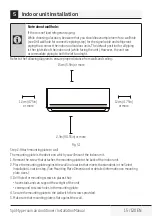
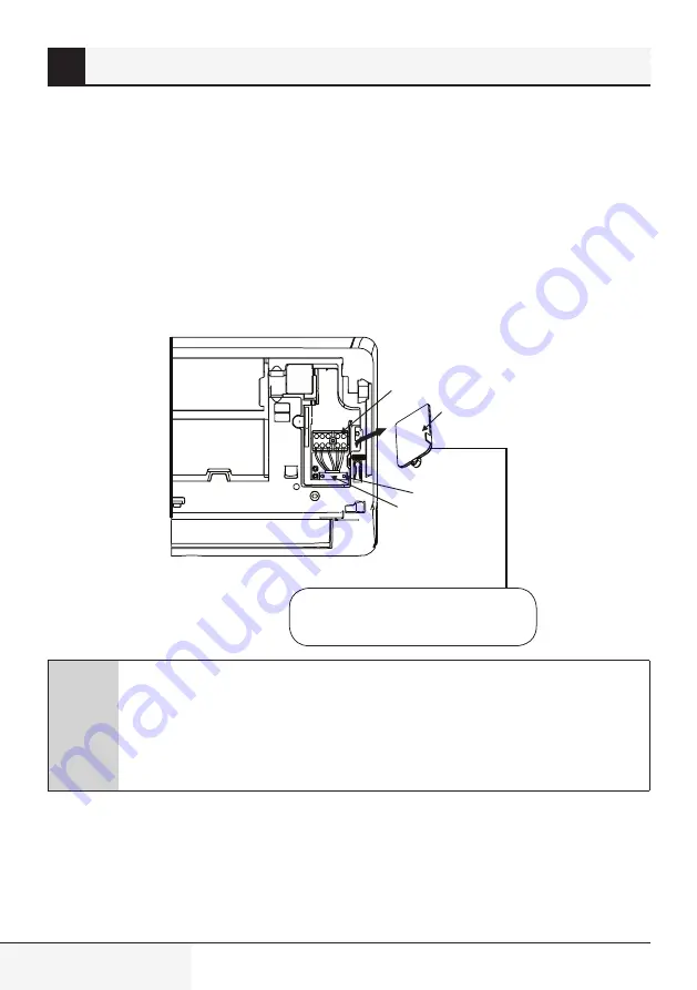
3. Using a screwdriver, open the wire box cover on the right side of the unit. This will reveal the
terminal block.
Terminal block
Wire cover
Screw
Cable clamp
Fig. 5.9
The Wiring Diagram is located on the inside
of the indoor unit’s wire cover.
A
Warning
All wiring must performed strictly in accordance with the
wiring diagram located on the inside of the indoor unit s
’wire cover.
4. Unscrew the cable clamp below the terminal block and place it to the side.
5. Facing the back of the unit, remove the plastic panel on the bottom left-hand side.
6. Feed the signal wire through this slot, from the back of the unit to the front.
7. Facing the front of the unit, match the wire colors with the labels on the terminal block, connect the
u-lug and and firmly screw each wire to its corresp onding terminal.
5
Indoor unit installation
Summary of Contents for BEVPI 090
Page 118: ......
Page 119: ......
Page 120: ...www beko com ...
Page 121: ...Air conditioner remote control User Manual EN ...
Page 128: ...8 24 EN Air conditioner remote control User Manual 3 Handling the remote control ...
Page 142: ......
Page 143: ......
Page 144: ...www beko com ...
Page 145: ......
Page 166: ......
Page 167: ......
Page 168: ...www beko com ...

