background image

10 / 44 EN

Free match split type air conditioner / Installation Manual

Table 5.1

Number of units that can be 

used together

Connected units

1-5 units

Compressor stop/start 

frequency

Stop time

3 min or more

Power source voltage

voltage fluctuation

within ±10% of rated voltage

voltage drop during start

within ±15% of rated voltage

interval unbalance

within ±3% of rated voltage

Table 5.2

Unit: m/ft.

1 drive 2

1 drive 3

1 drive 4

1 drive 5

Max. length for all rooms

30/98.4

45/147.6 60/196.8

75/246

Max. length for one indoor unit

25/82

30/98.4

35/114.8

35/114.8

Max. height different 

between indoor and 

outdoor unit

OU higher than IU

15/49

15/49

15/49

15/49

OU lower than IU

15/49

15/49

15/49

15/49

Max. height different between indoor units

10/32.8

10/32.8

10/32.8

10/32.8

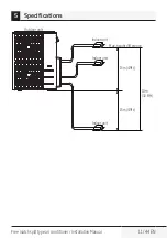
When installing multiple indoor units with a single outdoor unit, ensure that the length of the 

refrigerant pipe and the drop height between the indoor and outdoor units meet the requirements 

illustrated in the following diagram:

Specifications

Summary of Contents for BNFI 090

Page 1: ...Freematchsplittype airconditioner Installation Manual EN BNFI 090 BNFI 120 BNFI 180 BNFO 181 BNFO 211 BNFO 281 ...

Page 2: ...ou handover the product to someone else give the user manual as well Follow all warnings and information in the user manual Meanings of the symbols Following symbols are used in the various section of this manual C Important information or useful hints about usage A Warning for hazardous situations with regard to life and property Warning to actions that must never perform B Warning for electric s...

Page 3: ... indoor unit 19 7 Refrigerant piping connection 20 7 1 Safety precautions 20 7 2 Refrigerant piping connection instructions 20 8 Wiring 25 8 1 Safety precautions 25 8 2 Outdoor unit wiring 26 8 3 Wiring figure 27 9 Air evacuation 33 9 1 Safety precautions 33 9 2 Evacuation in structions 33 9 3 Safety and leakage check 36 10Test run 38 10 1 Before test run 38 10 2 Test run instructions 38 11 Functi...

Page 4: ...5 8 depending on models Drain joint some models 1 Seal ring some models 1 Connecting pipe assembly Liquid side Ø6 35 Parts you must purchase Consult a technician for the proper size Ø9 52 Gas side Ø9 52 Ø12 7 Ø15 9 Owner s manual 1 Installation manual 1 Transfer connector packed with the indoor or outdoor unit depending on models C Note Pipe size may differ from appliance to appliance To meet diff...

Page 5: ...nnot fasten on a small cord use the cord protection rubber ring supplied with accessories to wrap around the cord Then fix it in place with the cord clamp 1 on some models Optional accessories There are two types of remote controls wired and wireless Select a remote controller based on customer preferences and requirements and install in an appropriate place Refer to catalogues and technical liter...

Page 6: ...hniciansshouldinstall repairand servicethisairconditioningunit Improper installation may result in electrical shock short circuit leaks fire or other damage to the equipment and personal property Strictlyfollowtheinstallationinstructionssetforthinthismanual Improperinstallationmayresultinelectricalshock shortcircuit leaks fireorotherdamagetotheequipment Beforeyouinstalltheunit considerstrongwinds ...

Page 7: ...leaserefertotherelevantlabelontheunititself Installation service maintenanceandrepairofthisunit mustbeperformedbyacertifiedtechnician Productuninstallationandrecyclingmustbeperformed byacertifiedtechnician Ifthesystemhasaleak detectionsysteminstalled it mustbecheckedforleaksatleastevery12months Whentheunitischeckedforleaks properrecord keeping ofallchecksisstronglyrecommended 2 Safety instructions...

Page 8: ...Installation Manual Installation order 1 2 L N 3 Install the outdoor unit Page 9 Connect the refrigerant pipes Page 12 Connect the wires Page 14 5 MC MC 4 Perform a test run Page 22 Evacuate the refrigeration system Page 20 3 Installation overview ...

Page 9: ...ethan200cm More than 12cm More than 12cm More than 12cm More than 12cm Morethan 60cm More than 60cm Fig 4 1 4 2 Safety precautions A Warning This illustration is for demonstration purposes only The actual shape of your air condtioner may be slightly different Copperlinesmustbeindependentlyinsulated A Warning To prevent wall damage use a stud finder to locate studs A minimum pipe run of 3 metres is...

Page 10: ...rive 3 1 drive 4 1 drive 5 Max length for all rooms 30 98 4 45 147 6 60 196 8 75 246 Max length for one indoor unit 25 82 30 98 4 35 114 8 35 114 8 Max height different between indoor and outdoor unit OU higher than IU 15 49 15 49 15 49 15 49 OU lower than IU 15 49 15 49 15 49 15 49 Max height different between indoor units 10 32 8 10 32 8 10 32 8 10 32 8 When installing multiple indoor units with...

Page 11: ...Free match split type air conditioner Installation Manual 11 44 EN Outdoor unit Indoor unit Max height difference 15m 49ft 15m 49ft 10m 32 8ft Indoor unit Indoor unit 5 Specifications ...

Page 12: ...and outlet must not be obstructed or exposed to strong wind Ensure the location of the unit will not be subject to snowdrifts accumulation of leaves or other seasonal debris If possible provide an awning for the unit Ensure the awning does not obstruct airflow The installation area must be dry and well ventilated There must be enough room to install the connecting pipes and cables and to access th...

Page 13: ...he location is exposed to strong winds for example near a seaside the unit must be placed against the wall to shelter it from the wind If necessary use an awning See Fig 6 1 6 2 Install the indoor and outdoor units cables and wires at least 1 meter from televisions or radios to prevent static or image distortion Depending on the radio waves a 1 meter distance may not be enough to eliminate all int...

Page 14: ...14 44 EN Free match split type air conditioner Installation Manual Split type outdoor unit Refer to Fig 6 4 6 5 6 6 6 10 and Table 6 1 W H Fig 6 4 W H Fig 6 5 6 Outdoor unit installation ...

Page 15: ... 335 13 2 900x860x315 35 4x33 85x12 4 590 23 2 333 13 1 945x810x395 37 2x31 9x15 55 640 25 2 405 15 95 990x965x345 38 98x38x13 58 624 24 58 366 14 4 938x1369x392 36 93x53 9x15 43 634 24 96 404 15 9 900x1170x350 35 4x46x13 8 590 23 2 378 14 88 800x554x333 31 5x21 8x13 1 514 20 24 340 13 39 845x702x363 33 27x27 6x14 3 540 21 26 350 13 8 946x810x420 37 2x31 9x16 53 673 26 5 403 15 87 946x810x410 37 2...

Page 16: ...e 1 2H L H 30 cm 11 8 or more L H Can not be installed L H A 25 cm 9 8 or more 25 cm 9 8 or more 150 cm 59 or more 60 cm 23 6 or more 300 cm 118 or more Fig 6 7 C Note Theminimumdistancebetweentheoutdoorunitandwallsdescribedinthe installationguidedoesnotapplytoairtightrooms Besuretokeeptheunitunobstructedin atleasttwoofthethreedirections M N P SeeFig 6 8 6 Outdoor unit installation ...

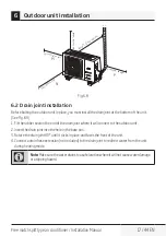
Page 17: ...om of the unit See Fig 6 9 1 Fit the rubber seal on the end of the drain joint where it will connect to the outdoor unit 2 Insert the drain joint into the hole in the base pan 3 Rotate the drain joint 90 until it clicks in place and faces the front of the unit 4 Connect a drain hose extension not included to the drain joint to redirect water from the unit during heating mode C Note Makesurethewate...

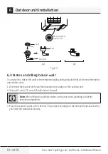
Page 18: ... will connect the indoor and outdoor units 1 Determine the location of the wall hole based on the location of the outdoor unit 2 Using a 65 mm 2 5 core drill drill a hole in the wall C Note When drilling the wall hole make sure to avoid wires plumbing and other sensitive components 3 Place the protective wall cuff in the hole This protects the edges of the hole and helps seal it when you finish th...

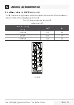
Page 19: ...it can only be connected with an A system If there are two 24K indoor units they can be connected with A and B systems See Fig 6 10 Table 6 3 Connective pipe size of an A and B system unit inch Indoor unit capacity Btu h Liquid Gas 7K 9K 12K 1 4 3 8 12K 18K 1 4 1 2 7K 9K 12K 3 8 5 8 Fig 6 10 6 Outdoor unit installation ...

Page 20: ...there is refrigerant leakage during the installation Leaked refrigerant gas is both toxic and flammable Ensure there is no refrigerant leakage after completing the installation work 7 2 Refrigerant piping connection instructions A Warning The branching pipe must be installed horizontally An angle of more than 10 may cause malfunction Do not install the connecting pipe until both indoor and outdoor...

Page 21: ... the pipe 2 Using a reamer or deburring tool remove all burrs from the cut section of the pipe Pipe Reamer Point down Fig 7 2 Step 3 Flare pipe ends Proper flaring is essential to achieve an airtight seal 1 After removing burrs from cut pipe seal the ends with PVC tape to prevent foreign materials from entering the pipe 2 Sheath the pipe with insulating material 3 Place flare nuts on both ends of ...

Page 22: ... in table 7 1 Table 7 1 Piping extension beyond flare form Pipe gauge Tightening torque Flare dimension A Unit mm Inch Flare shape Min Max Ø 6 4 14 2 17 2 N m 144 176 kgf cm 8 3 0 3 8 3 0 3 45 2 90 4 A R0 4 0 8 Fig 7 5 Ø 9 5 32 7 39 9 N m 333 407 kgf cm 12 4 0 48 12 4 0 48 Ø 12 7 49 5 60 3 N m 504 616 kgf cm 15 4 0 6 15 8 0 6 Ø 15 9 61 8 75 4 N m 630 770 kgf cm 18 6 0 7 19 0 74 Ø 19 1 97 2 118 6 N...

Page 23: ...ing Flare nut Pipe Fig 7 6 3 Tighten the flare nut as tightly as possible by hand 4 Using a spanner grip the nut on the unit tubing 5 While firmly gripping the nut use a torque wrench to tighten the flare nut according to the torque values in table 7 1 C Note Usebothaspannerandatorquewrenchwhenconnectingordisconnectingpipes to fromtheunit Fig 7 7 A Warning Ensure to wrap insulation around the pipi...

Page 24: ...otherwires Whilebundlingtheseitems together donotintertwineorcrossthesignalcablewithanyotherwiring 7 Thread this pipeline through the wall and connect it to the outdoor unit 8 Insulate all the piping including the valves of the outdoor unit 9 Open the stop valves of the outdoor unit to start the flow of the refrigerant between the indoor and outdoor unit A Warning Check to make sure there is no re...

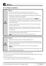
Page 25: ...se overheating at the connection points fire and electrical shock Ensure that main supply connection is made through a switch that disconnects all poles with contact gap of a least 3mm 0 118 Do not modify the length of the power cord or use an extension cord A Warning Connect the outdoor wires before connecting theindoor wires Make sure you ground the unit The grounding wire should be away from ga...

Page 26: ...nd signal cables north america Rated current of appliance A AWG 7 18 7 13 16 13 18 14 18 25 12 25 30 10 Table 8 2 Other regions Rated current of appliance A Nominal cross sectional area mm 6 0 75 6 10 1 10 16 1 5 16 25 2 5 25 32 4 32 45 6 b Using wire strippers strip the rubber jacket from both ends of signal cable to reveal about 15cm 5 9 of the wires inside c Strip the insulation from the ends o...

Page 27: ...rmly screw the u lug of each wire to its corresponding terminal 4 Clamp down the cable with designated cable clamp 5 Insulate unused wires with electrical tape Keep them away from any electrical or metal parts 6 Reinstall the cover of the electric control box 8 3 Wiring figure A Warning Connect the connective cables to the terminals as identified with their matching numbers on the terminal block o...

Page 28: ...l Power Power C Note Refertothefollowingfiguresifend userswishtoperformtheirownwiring Runthemainpowercordthroughthelowerline outletofthecordclamp One two models Power Power Power Power Model A Model B Model C Model D Power Power Power Model E Model F Model G 8 Wiring ...

Page 29: ...tional part Used to hitch to the connective cable of indoor and outdoor units after installation C Note Pleaserefertothefollowingfiguresifend userswishtoperformtheirownwiring One three models Power Power Power Model A Model B Model C Power Power Power Model D Model E Model F Power Model G 8 Wiring ...

Page 30: ...30 44 EN Free match split type air conditioner Installation Manual One four models Power Power Model A Model B Power Power Model C Model D Power Power Model E Model F Power Model G 8 Wiring ...

Page 31: ...Free match split type air conditioner Installation Manual 31 44 EN One five models Power Power Model A Model B Power Power Model C Model D Power Power Model E Model F Power Model G 8 Wiring ...

Page 32: ...r the power source Confirm that electrical capacity is sufficient Confirm that starting voltage is maintained at more than 90 percent of the rated voltage marked on the name plate Confirm that the cable thickness is as specified in the power source specifications Always install an earth leakage circuit breaker in wet or moist areas The following can be caused by a drop in voltage vibration of a ma...

Page 33: ...ng a manifold gauge and a vacuum pump read their operation manuals to make sure you know how to use them properly Manifold gauge Low pressure valve Compound gauge Pressure gauge High pressure valve Charge hose Vacuum pump 76cmHg Low pressure valve Charge hose Fig 9 1 1 Connect the manifold gauge s charge hose to the service port on the outdoor unit s low pressure valve 2 Connect the manifold gauge...

Page 34: ... make sure that there is no change in pressure It should read slightly higher than the atmospheric pressure 10 Remove the charge hose from the service port 11 Using hexagonal wrench fully open both the high pressure and low pressure valves C Openvalvestemsgently Whenopeningthevalvestems turnthehexagonalwrenchuntilithitsagainstthestopper Donottrytoforcethevalvetoopenfurther 12 Tighten valve caps by...

Page 35: ...s N 3 one three models N 4 one four models N 5 one five models Depending on the length of connective piping or the pressure of the evacuated system you made need to add refrigerant Refer to table below for refrigerant amounts to be added Additional refrigerant per pipe length Connective pipe length Air purging method Additional refrigerant R410A Pre charge pipe length ft m Standard pipe lengthxN V...

Page 36: ... on During a test operation after completed installation use the electroprobe and multimeter to perform an electrical leakage check Turn off the unit immediately if leakage happens Try and evaluate different solutions until the unit operates properly Gas leak check 1 Soap water method Apply a soap water solution or a liquid neutral detergent on the indoor unit connection or outdoor unit connection...

Page 37: ...lit type air conditioner Installation Manual 37 44 EN Indoor unit check point Outdoor unit check point Fig 9 4 A B C D are points for the one four type A B C D and E are points for the one five type 9 Air evacuation ...

Page 38: ... Warning Failure to perform the test run may result in unit damage property damage or personal injury 10 2 Test run instructions 1 Open both the liquid and gas stop valves 2 Turn on the main power switch and allow the unit to warm up 3 Set the air conditioner to cool mode 4 For theindoor unit a Ensure the remote control and its buttons work properly b Ensure the louvers move properly and can be ch...

Page 39: ... noise and water generated by the unit do not disturb your neighbors or pose a safety hazard C Note If the unit malfunctions or does not operate according to your expectations please refer to the Troubleshooting section of the owner s manual before calling customer service 10 Test run ...

Page 40: ...ting that this function is working Approximately 5 10 minutes after the switch is pressed the CE disappears meaning that the wiring piping error is corrected and all wiring piping is properly connected Check switch LED display B A B A B A B A B A B A Indoor unit B Indoor unit B Outdoor unit Outdoor unit Correct wiring Incorrect wiring Incorrect wiring Terminal block Terminal block Liquid Gas pipe ...

Page 41: ...e this function 1 Check that outside temperature is above 5 C This function does not work when outside temperature is not above 5 C 2 Check that the stop valves of the liquid pipe and gas pipe are open 3 Turn on the breaker and wait at least 2 minutes 4 Press the check switch on the outdoor PCB board unit LED display CE 11 Function of automatic wiring piping correction ...

Page 42: ... recycling should be carried out by natural persons that hold relevant certificates If the system has a leakage detection system installed leakage checks should be performed at least every 12 months make sure system operate properly If product must be performed leakage checks it should specify Inspection cycle establish and save records of leakage checks C Note For hermetically sealed equipment po...

Page 43: ...Manufactured by Arcelik A S Karaagac Cd No 2 6 34445 Sutluce Beyoglu Istanbul Turkey ...

Page 44: ...www beko com ...

Page 45: ...Condizionatore Free Match Tipo Split Manuale d installazione IT BNFI 090 BNFI 120 BNFI 180 BNFO 181 BNFO 211 BNFO 281 ...

Page 46: ...ualcun altro gli fornisca anche il manuale dell utente Segua tutte le avvertenze e le informazioni riportate nel manuale dell utente Significato dei simboli I seguenti simboli sono utilizzati in diverse sezioni di questo manuale C Informazioni importanti o suggerimenti pratici sull utilizzo A Avvertenza situazioni di pericolo relative a vita e proprietà Avvertenza operazioni da non eseguire B Avve...

Page 47: ... refrigerante 20 7 1 Misure di sicurezza 20 7 2 Istruzioni per il collegamento della tubazione refrigerante 20 8 Collegamento elettrico 25 8 1 Misure di sicurezza 25 8 2 Cablaggio esterno dell unità 26 8 3 Schema di cablaggio 27 9 Scarico aria 33 9 1 Misure di sicurezza 33 9 2 Istruzioni per lo svuotamento 33 9 3 Verifica sicurezza e perdite 36 10Esecuzione del test 38 10 1 Prima di eseguire il te...

Page 48: ... modelli 1 Anello di guarnizione alcuni modelli 1 Gruppo tubazione di collegamento Condotto del liquido Ø6 35 Componenti da acquistare Consultare un tecnico per le dimensioni appropriate Ø9 52 Condotto del gas Ø9 52 Ø12 7 Ø15 9 Manuale del proprietario 1 Manuale d installazione 1 Connettore di trasferimento in dotazione con l unità esterna o interna a seconda dei modelli C Nota Ladimensionedella c...

Page 49: ...l morsetto non si fissa su un cavo piccolo usare l anello in gomma per la protezione del cavo fornito con gli accessori per avvolgerlo quindi fissarlo con il morsetto 1 su alcuni modelli Accessori opzionali Esistono due tipi di telecomando con fili e senza fili Scegliere un telecomando in base alle preferenze e ai requisiti del cliente e installarlo nel luogo appropriato Leggere nei cataloghi e ne...

Page 50: ...atori appositamente progettati Solo tecnici opportunamente formati e certificati installano riparano ed eseguono la manutenzione di questo condizionatore Un installazione non corretta può provocare scosse elettriche cortocircuiti perdite incendi o altri danni all attrezzatura e alla proprietà personale Seguire rigorosamente le istruzioni per l installazione del presente manuale Un installazione no...

Page 51: ...fare riferimento alla relativa etichetta apposta sull unità stessa L installazione l assistenza la manutenzione e la riparazione di questa unità devono essere effettuate da un tecnico certificato La disinstallazione e lo smaltimento del prodotto devono essere effettuati da un tecnico certificato Se l unità dispone di un sistema di rilevamento perdite è necessario verificare l eventuale presenza di...

Page 52: ...one Procedura di installazione 1 2 L N 3 Installare l unità esterna Pagina 9 Collegare i tubi del refrigerante Pagina 12 Collegare i cavi Pagina 14 5 MC MC 4 Eseguire una prova di funzionamento Pagina 22 Svuotare l impianto di refrigerazione Pagina 20 3 Installazione ...

Page 53: ...00cm Più di 12 cm Più di 12 cm Più di 12 cm Più di 12 cm Piùdi 60cm Più di 60 cm Fig 4 1 4 2 Misure di sicurezza A Avvertenza Questa illustrazione ha uno scopo puramente dimostrativo La forma effettiva del condizionatore può essere leggermente diversa Isolare i cavi in rame a parte A Avvertenza Per evitare danni alla parete usare usare un cercametalli Una tubazione lunga almeno 3 metri è richiesta...

Page 54: ...5 2 Unità m piedi 1 drive 2 1 drive 3 1 drive 4 1 drive 5 Massima lunghezza per tutti i locali 30 98 4 45 147 6 60 196 8 75 246 Massima lunghezza per un unità interna 25 82 30 98 4 35 114 8 35 114 8 Massima differenza in altezza tra unità interna ed esterna OU più alta di IU 15 49 15 49 15 49 15 49 OU più bassa di IU 15 49 15 49 15 49 15 49 Massima differenza in altezza tra le unità interne 10 32 ...

Page 55: ...zionatore Free Match Tipo Split Manuale d installazione 11 44 IT Unità esterna Unità interna Massima differenza in altezza 15 m 49 piedi 15 m 49 piedi 10 m 32 8 piedi Unità interna Unità interna 5 Specifiche ...

Page 56: ...e ostruiti o esposti al vento forte Verificare che il luogo di installazione dell unità non sia esposto a cumuli di neve di foglie o altri rifiuti stagionali Se possibile predisporre un tendone per l unità Verificare che il tendone non ostruisca il flusso dell aria L area di installazione deve essere asciutta e ben ventilata Assicurarsi che vi sia uno spazio sufficiente per installare i tubi e i c...

Page 57: ...sempio vicino alla costa l unità deve essere posizionata contro la parete per ripararla Se necessario usare un tendone Vedere Fig 6 1 6 2 Installare le unità esterne ed interne i cavi e i fili ad almeno 1 metro di distanza da televisioni e radio per evitare la distorsione statica e dell immagine A seconda delle onde radio una distanza di 1 metro potrebbe non essere sufficiente per eliminare tutte ...

Page 58: ...14 44 IT Condizionatore Free Match Tipo Split Manuale d installazione Unità esterna tipo split Vedere le Fig 6 4 6 5 6 6 6 10 e la Tabella 6 1 W H Fig 6 4 W H Fig 6 5 6 Installazione dell unità esterna ...

Page 59: ...60 22 335 13 2 900x860x315 35 4x33 85x12 4 590 23 2 333 13 1 945x810x395 37 2x31 9x15 55 640 25 2 405 15 95 990x965x345 38 98x38x13 58 624 24 58 366 14 4 938x1369x392 36 93x53 9x15 43 634 24 96 404 15 9 900x1170x350 35 4x46x13 8 590 23 2 378 14 88 800x554x333 31 5x21 8x13 1 514 20 24 340 13 39 845x702x363 33 27x27 6x14 3 540 21 26 350 13 8 946x810x420 37 2x31 9x16 53 673 26 5 403 15 87 946x810x410...

Page 60: ...2H L H 30 cm 11 8 o più L H Non installabile L H A 25 cm 9 8 pollici o più 25 cm 9 8 o più 150 cm 59 o più 60 cm 23 6 o più 300 cm 118 o più Fig 6 7 C Nota La distanza minima tra l unità esterna e le pareti descritta nella guida all installazione non vale per locali ermetici Tenere libera l unità in almeno due delle tre direzioni M N P Vedere Fig 6 8 6 Installazione dell unità esterna ...

Page 61: ...are la Fig 6 9 1 Fissare la guarnizione in gomma all estremità del tubo di scarico dove si collega all unità esterna 2 Inserire il tubo di scarico nel foro nella bacinella alla base dell unità 3 Ruotare il tubo di scarico di 90 finché non scatta in posizione rivolto verso la parte anteriore dell unità 4 Collegare un tubo di prolunga per lo scarico non incluso al tubo di scarico per direzionare l a...

Page 62: ...he collega l unità esterna e interna 1 Determinare la posizione del foro da praticare nella parete in base a quella dell unità esterna 2 Usando una punta da 65 mm 2 5 l praticare un foro nella parete C Nota Mentre si pratica il foro nella parete evitare cavi elettrici tubazioni idriche e altri componenti sensibili 3 Inserire il cappuccio di protezione per la parete nel foro Ciò consente di protegg...

Page 63: ...legata solo ad un sistema A Se vi sono due unità interne 24K possono essere collegate a sistemi A e B Vedere la Fig 6 10 Tabella 6 3 Dimensione del tubo di connessione di un sistema A e B unità pollici Capacità dell unità interna Btu h Liquido Gas 7K 9K 12K 1 4 3 8 12K 18K 1 4 1 2 7K 9K 12K 3 8 5 8 Fig 6 10 6 Installazione dell unità esterna ...

Page 64: ...one Il gas refrigerante fuoriuscito è tossico e infiammabile Verificare che non vi siano perdite di refrigerante dopo il completamento dei lavori di installazione 7 2 Istruzioni per il collegamento della tubazione refrigerante A Avvertenza Il tubo di derivazione deve essere installato orizzontalmente Un angolo superiore a 10 può causare un malfunzionamento Non installare il tubo di connessione fin...

Page 65: ...ite un alesatore o uno sbavatore rimuovere tutte le bave dalla sezione tagliata del tubo Tubo Alesatore Verso il basso Fig 7 2 Passaggio 3 Svasare le estremità dei tubi Una svasatura corretta è essenziale per sigillare a tenuta stagna il tubo 1 Dopo la rimozione delle bave dal tubo tagliato sigillare le estremità con del nastro in PVC per evitare che sostanze estranee penetrino nel tubo 2 Rivestir...

Page 66: ...n è completamente svasato Svasare il tubo secondo le dimensioni indicate nella tabella 7 1 Tabella 7 1 Estensione del tubo oltre la forma svasata Calibro per tubi Coppia di serraggio Dimensione della svasatura A Unità mm Ipollici Forma svasata Min Max Ø 6 4 14 2 17 2 N m 144 176 kgf cm 8 3 0 3 8 3 0 3 45 2 90 4 A R0 4 0 8 Fig 7 5 Ø 9 5 32 7 39 9 N m 333 407 kgf cm 12 4 0 48 12 4 0 48 Ø 12 7 49 5 6...

Page 67: ...si andranno a collegare Tubo dell unità interna Dado svasato Tubo Fig 7 6 3 Stringere il dado svasato il più stretto possibile a mano 4 Tramite una chiave stringere il dado sul tubo dell unità 5 Afferrando saldamente il dado usare una chiave dinamometrica per serrare il dado svasato secondo i valori di coppia della tabella 7 1 C Nota Usare una chiave inglese e una chiave dinamometrica per collegar...

Page 68: ... il cavo del segnale con altri cavi Quando si avvolgono questi elementi insieme non intrecciare il cavo del segnale con alcun altro cavo 7 Inserire questa tubazione nella parete e collegarla all unità esterna 8 Isolare tutte le tubazioni comprese le valvole dell unità esterna 9 Aprire le valvole di arresto dell unità esterna per avviare il flusso di refrigerante tra l unità interna ed esterna A Av...

Page 69: ...nei punti di connessione incendi e scosse elettriche Verificarechelaconnessionedialimentazioneprincipaleavvengaattraversoun interruttorechescolleghituttiipoli conaperturadeicontattidialmeno3mm 0 118 Non modificare la lunghezza del cavo di alimentazione o usare una prolunga A Avvertenza Collegare i cavi esterni e poi quelli interni Assicurarsidieffettuareilcollegamentoditerradell unità Ilcavodimess...

Page 70: ... sezione dei cavi di alimentazione e di segnale Nord America Corrente nominale assorbita dall apparecchiatura A AWG 7 18 7 13 16 13 18 14 18 25 12 25 30 10 Tabella 8 2 Altre regioni Corrente nominale assorbita dall apparecchiatura A Area di intersezione nominale mm 6 0 75 6 10 1 10 16 1 5 16 25 2 5 25 32 4 32 45 6 b Utilizzando dei spellacavi togliere il rivestimento in gomma da entrambe le estrem...

Page 71: ...lori con le etichette sulla morsettiera collegare i capicorda a U ai morsetti corrispondenti e serrarli 4 Bloccare il cavo con il relativo morsetto 5 Isolare i conduttori non utilizzati con nastro isolante Tenerli lontani da parti elettriche o metalliche 6 Rimontare il coperchio del quadro di controllo elettrico 8 3 Schema di cablaggio A Avvertenza Collegare i cavi ai morsetti come mostrato abbina...

Page 72: ...proprio fare riferimento alle immagini che seguono Far passare il cavo dell alimentazione di rete attraverso l uscita inferiore del morsetto Modelli Uno Due Alimentazione Alimentazione Alimentazione Alimentazione Modello A Modello B Modello C Modello D Alimentazione Alimentazione Alimentazione Modello E Modello F Modello G 8 Collegamento elettrico ...

Page 73: ... dell unità esterna ed interna dopo l installazione C Nota Se si desidera effettuare il cablaggio in proprio fare riferimento alle immagini che seguono Modelli Uno Tre Alimentazione Alimentazione Alimentazione Modello A Modello B Modello C Alimentazione Alimentazione Alimentazione Modello D Modello E Modello F Alimentazione Modello G 8 Collegamento elettrico ...

Page 74: ...Split Manuale d installazione Modelli Uno Quattro Alimentazione Alimentazione Modello A Modello B Alimentazione Alimentazione Modello C Modello D Alimentazione Alimentazione Modello E Modello F Alimentazione Modello G 8 Collegamento elettrico ...

Page 75: ...uale d installazione 31 44 IT Modelli Uno Cinque Alimentazione Alimentazione Modello A Modello B Alimentazione Alimentazione Modello C Modello D Alimentazione Alimentazione Modello E Modello F Alimentazione Modello G 8 Collegamento elettrico ...

Page 76: ...rica sia sufficiente Accertarsi che la tensione di avviamento si mantenga ad oltre il 90 della tensione nominale specificata sulla targhetta dell unità Verificare che la sezione del cavo sia quella indicata nelle specifiche della fonte di alimentazione Per evitare dispersioni verso terra in ambienti esposti all umidità e o alla pioggia installare sempre un interruttore differenziale Una caduta di ...

Page 77: ...r lo svuotamento Prima di utilizzare un manometro e una pompa a depressione leggere i relativi manuali di istruzioni Collettore a manometri Valvola di bassa pressione Manometro Indicatore della pressione Valvola di alta pressione Tubo di ricarica Pompa a vuoto 76 cmHg Valvola di bassa pressione Tubo di ricarica Fig 9 1 1 Collegare il tubo flessibile di ricarica del manometro all attacco di servizi...

Page 78: ...ometro per un minuto per accertarsi che non vi siano cambi di pressione Il valore dovrebbe essere leggermente superiore alla pressione atmosferica 10 Rimuovere il tubo di ricarica dalla porta di servizio 11 Tramite una chiave esagonale aprire completamente sia la valvola di alta pressione che quella di bassa pressione C Aprire delicatamente gli steli delle valvole Quando si aprono gli steli delle ...

Page 79: ... 4 modelli uno quattro N 5 modelli uno cinque A seconda della lunghezza della tubazione di collegamento o della pressione del sistema svuotato potrebbe essere necessario aggiungere refrigerante Per le quantità di refrigerante da aggiungere fare riferimento alla tabella che segue Refrigerante aggiuntivo per lunghezza del tubo Lunghezza del tubo di collegamento Metodo di sfiato dell aria Refrigerant...

Page 80: ...zione verificare la dispersione elettrica mediante sonda e multimetro Disattivare l unità appena si verifica una dispersione Valutare soluzioni differenti fino ad ottenere il corretto funzionamento dell unità Verifica della presenza di fughe di gas 1 Metodo acqua saponata Per verificare eventuali perdite nei punti di collegamento della tubazione con un pennello morbido applicare una soluzione di a...

Page 81: ...Tipo Split Manuale d installazione 37 44 IT Punto di controllo unità interna Punto di controllo unità esterna Fig 9 4 A B C e D sono i punti per il tipo uno quattro A B C D ed E sono i punti per il tipo uno cinque 9 Scarico aria ...

Page 82: ...ere come conseguenza danni all unità o a cose e lesioni personali 10 2 Istruzioni per il test di funzionamento 1 Aprire le valvole di intercettazione del liquido e del gas 2 Attivare l interruttore generale dell alimentazione di rete e far riscaldare l unità 3 Impostare il condizionatore in modalità raffreddamento 4 Per l unità interna a Assicurarsi che il telecomando ed i relativi pulsanti funzio...

Page 83: ... il funzionamento c Assicurarsi che vento rumore ed acqua prodotti dall unità non disturbino i vicini o creino situazioni di pericolo C Nota In caso di malfunzionamenti o funzionamento insoddisfacente prima di contattare l assistenza tecnica fare riferimento alla sezione Risoluzione dei problemi del Manuale utente 10 Esecuzione del test ...

Page 84: ...a che la funzione è attiva Dopo circa 5 10 minuti il messaggio CE scompare confermando che l errore di cablaggio tubazioni è stato corretto e che cablaggio tubazioni sono correttamente collegati Interruttore di controllo Display a LED B A B A B A B A B A B A Unità interna B Unità interna B Unità esterna Unità esterna Cablaggio corretto Cablaggio non corretto Cablaggio non corretto Blocco terminale...

Page 85: ...a temperatura esterna sia superiore a 5 C la funzione non si attiva in caso la temperatura esterna sia inferiore a 5 C 2 Verificare che le valvole di intercettazione del liquido e del gas siano aperte 3 Attivare l interruttore ed attendere almeno 2 minuti 4 Premere l interruttore di controllo sulla scheda PCB dell unità esterna fino a visualizzare CE sul display 11 Funzione di correzione automatic...

Page 86: ...ttuati da personale qualificato Se il sistema è dotato di dispositivo per il rilevamento delle perdite i controlli delle perdite devono essere eseguiti almeno ogni 12 mesi accertando che il sistema funzioni correttamente Ogni qual volta vengono eseguiti controlli delle perdite occorre specificare il ciclo di controllo creare e conservare dei registri concernenti le verifiche C Nota Non occorre ese...

Page 87: ...Prodotto da Arcelik A S Karaagac Cd No 2 6 34445 Sutluce Beyoglu Istanbul Turchia ...

Page 88: ...www beko com ...

Reviews: