Maintenance, troubleshooting, spare parts and dismantling
DRYPOINT® RS 15-550 HP50 NA
33
DAILY:
• Check whether the dew point indicated on the electronics is correct.
• Ensure that the condensate drain system functions properly.
• Make sure that the condenser is clean.
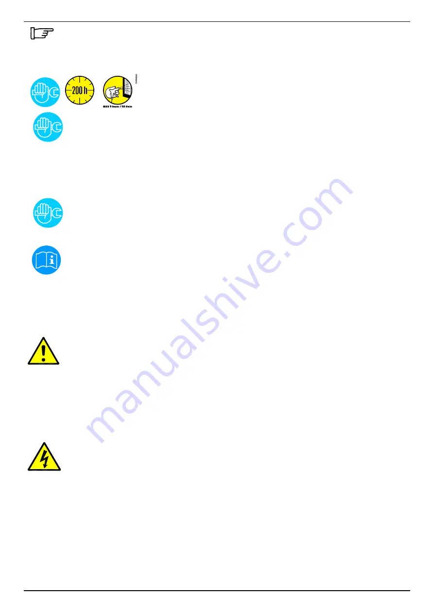
EVERY 200 HOURS OR MONTHLY
• Clean the condenser using an air jet (max. 2 bar / 30 psig) inside out. Make
sure not to damage the aluminium lamellae of the cooling package.
• Finally, verify the operation of the device.
EVERY 1,000 HOURS OR ANNUALLY
• Verify all screws, clamps and connections of the electric system to make sure that they are fastened
securely. Check the device for broken and ruptured cables or cables without insulation.
• Check the refrigeration cycle for signs of oil and refrigerant leaks.
• Measure the current strength and note it down. Ensure that the read values are within the permissible
limit values, as indicated in the specification table.
• Check the hose lines of the condensate drain and replace them, if required.
•
Finally, verify the operation of the device.
EVERY YEAR
• Clean housing and valve of BEKOMAT
• Replace BEKOMAT wearing parts
12.2 Troubleshooting
Certified skilled personnel
Installation works must exclusively be carried out by authorised and qualified skilled personnel. Prior to
undertaking any measures on the DRYPOINT® RS 15-550 HP50 NA high pressure compressed-air
refrigeration dryer, the certified skilled personnel shall read up on the device by carefully studying the
operating instructions. The operator is responsible for the adherence to these provisions. The respective
directives in force apply to the qualification and expertise of the certified skilled personnel.
For safe operation, the device must only be installed and operated in accordance with the indications in
the operating instructions. In addition, the national and operational statutory provisions and safety
regulations, as well as the accident prevention regulations required for the respective case of application,
need to be observed during employment. This applies accordingly when accessories are used.
Danger!
Compressed air!
Risk of serious injury or death through contact with quickly or suddenly escaping compressed
air or through bursting and/or unsecured plant components.
Compressed air is a highly dangerous energy source.
Never work on the dryer when the system is under pressure.
Never direct the compressed-air outlet or condensate drain hoses at persons.
The user is responsible for the proper maintenance of the dryer. Non-observance of the instructions in the
"Installation" and "Maintenance, troubleshooting, spare parts and dismantling" chapters leads to the
expiration of the guarantee. Improper maintenance may result in dangerous situations for the personnel
and/or the device.
Danger!
Supply voltage!
Contact with non-insulated parts carrying supply voltage involves the risk of an electric shock resulting in
injuries and death.
Only qualified and skilled personnel are authorised to run electrically-operated devices. Prior to undertaking
maintenance measures at the device, the following requirements must be met:
Make sure that the power supply is switched off and that the device is off and marked for maintenance
measures. Please also ensure that the power supply cannot be re-established during the works.
Summary of Contents for DRYPOINT RS 100-E HP50 NA
Page 22: ...22 DRYPOINT RS 15 550 HP50 NA 10 4 Technical data DRYPOINT RS 180 550 3phase HP50 NA 3 380 60 ...
Page 40: ...Appendices 40 DRYPOINT RS 15 550 HP50 NA 13 1 2 Dryer dimensions DRYPOINT RS 50 80 HP50 NA ...
Page 41: ...Appendices DRYPOINT RS 15 550 HP50 NA 41 13 1 3 Dryer dimensions DRYPOINT RS 100 140 HP50 NA ...
Page 42: ...Appendices 42 DRYPOINT RS 15 550 HP50 NA 13 1 4 Dryer dimensions DRYPOINT RS 180 350 HP50 NA ...
Page 43: ...Appendices DRYPOINT RS 15 550 HP50 NA 43 13 1 5 Dryer dimensions DRYPOINT RS 450 550 HP50 NA ...
Page 47: ...Appendices DRYPOINT RS 15 550 HP50 NA 47 13 2 2 Exploded diagram DRYPOINT RS 15 40 HP50 NA ...
Page 48: ...Appendices 48 DRYPOINT RS 15 550 HP50 NA 13 2 3 Exploded diagram DRYPOINT RS 50 80 HP50 NA ...
Page 49: ...Appendices DRYPOINT RS 15 550 HP50 NA 49 13 2 4 Exploded diagram DRYPOINT RS 100 140 HP50 NA ...
Page 59: ...Appendices DRYPOINT RS 15 550 HP50 NA 59 13 3 2 Electric diagram DRYPOINT RS 15 40 HP50 NA ...
Page 60: ...Appendices 60 DRYPOINT RS 15 550 HP50 NA 13 3 3 Electric diagram DRYPOINT RS 50 80 HP50 NA ...
Page 61: ...Appendices DRYPOINT RS 15 550 HP50 NA 61 13 3 4 Electric diagram DRYPOINT RS 100 140 HP50 NA ...
Page 62: ...Appendices 62 DRYPOINT RS 15 550 HP50 NA 13 3 5 Electric diagram DRYPOINT RS 180 260 HP50 NA ...
Page 63: ...Appendices DRYPOINT RS 15 550 HP50 NA 63 13 3 6 Electric diagram DRYPOINT RS 350 HP50 NA ...
Page 64: ...Appendices 64 DRYPOINT RS 15 550 HP50 NA 13 3 7 Electric diagram DRYPOINT RS 450 550 HP50 NA ...
Page 71: ...DRYPOINT RS 15 550 HP50 NA 71 ...


