6
4. Electrical connections
In order to guarantee trouble free operation you should observe the following instructions:
1.
The device is only permitted for operation with mains voltages of 100 – 260 Volts AC
and frequencies between 50 - 60 Hz.
2.
Please use the mains cable enclosed or one of equal quality and power capability. For
use in the US please cut off the German plug and connect it to your 220 V socket.
3.
In case of connection to an AC power generator,
you must check if the required
specifications under item 1 especially under full load conditions are fulfilled.
Ignoring the above can cause damage
and will exclude warranty.
4.
The system impedance of the device is 50 Ohms. In order to achieve optimum driving
level and maximum output power,
all load and source impedances should also be 50
Ohms. Deviations will automatically cause limitation of the specifications and shifting
of the threshold voltages of the protection circuits. Operation with no load connected
is not allowed.
5.
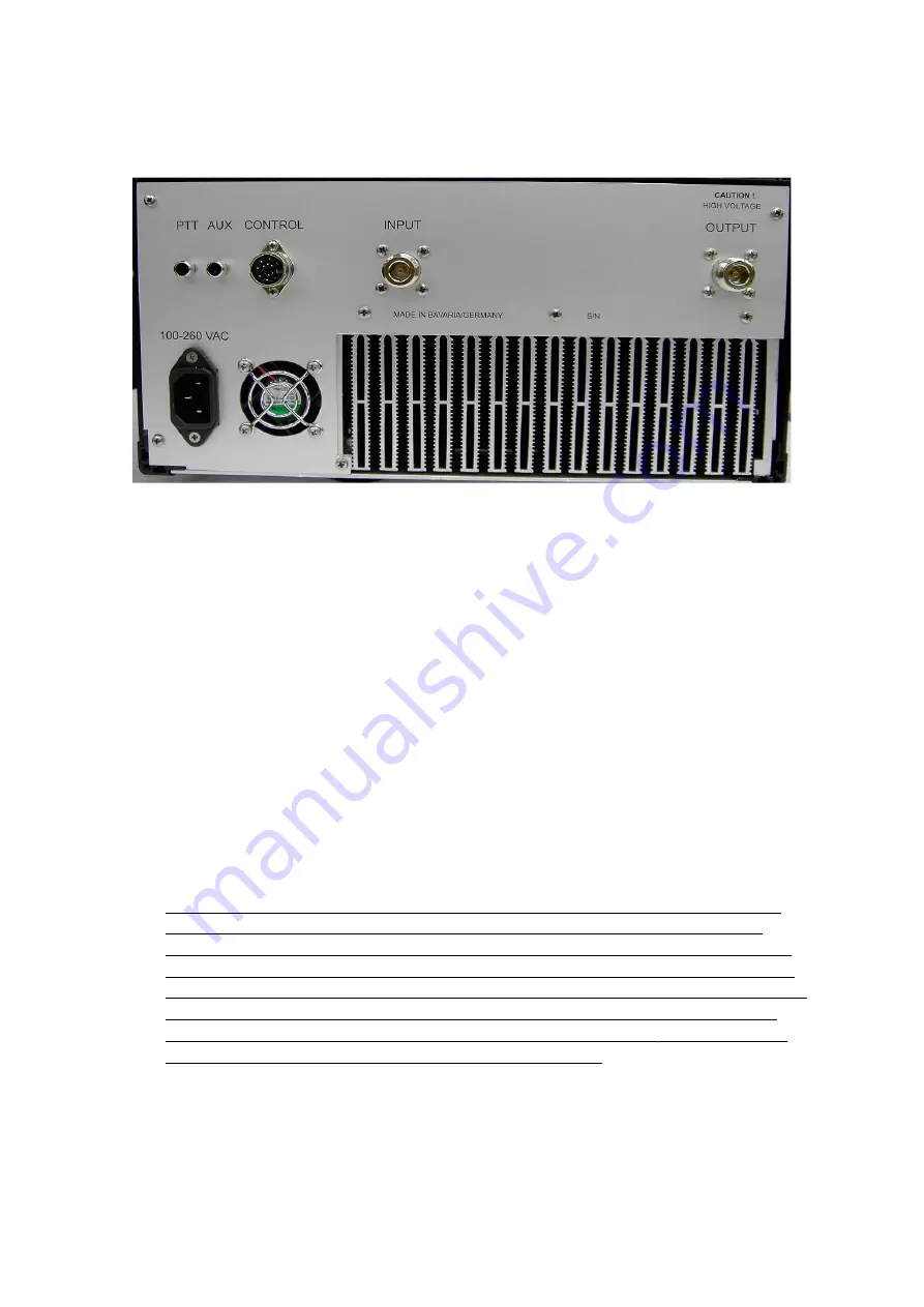
The RF connectors are N-type. Only high quality connectors with PTFE insulation
must be used. Neglecting will cause overload and damage of the connectors and
shifting of the thresholds of the protection circuits. Special care must be taken when
connecting the output cable to the output connector. If large and stiff low loss cables
are used a short and flexible cable/adapter solution must be interconnected. Otherwise
too much bending force will be applied to the rear panel and to the female N-jack.
When fastening any N-plug to this N-jack the use of a plyers or a
similar tool must
not be used!! Only strong finger tight fastening is allowed.
6.
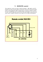
Switching the amplifier to transmit mode is accomplished via the PTT jack . Connect a
single wire cable of
up to 100 m length to the center pin. of the 5-pin A DC path to
ground of < 100 Ohm or a voltage < 0,5 Volt is sufficient to switch the amplifier to
transmit mode. It’s important to have a common ground connection between the
transceiver and the amplifier.
Summary of Contents for HLV-350
Page 1: ...1 HLV 350 Instruction Operations Manual ...
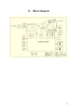
Page 13: ...13 11 Block diagram ...


