Cooker Hood / User Manual
17 / EN
7
Installation instructions
7.1 Wall drilling and bracket
fixing
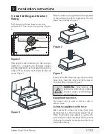
Drill holes with a Ø4 mm diameter on points
marked A, B, C, D on the mounting scheme. Figure
2
B
A
D
C
Ø4
A,B,C,D =
520
500
19
10
10
2 10
462±2
30
5
283
22
3±
2
248
50
Ø1
30
±2
28
MOUNTING TEMPLATE SCALE 1:1
SAGOMA DI MONTAGGIO RELAZIONE 1:1
ESTAMPA DE MONTAJE ESCALA 1:1
GABARIT POUR MONTAGE ECHELLE 1:1
MONTAGESCHABLONE MAßSTAB 1:1
AUSSCHNITT IM SCHRANK FÜR LUFTAUSTRITT
LINEA DI TAGLIO PER USCITA ARIA
RECORTE DEL ARMARIO PARA LA SALIDA DE AIRE
LIGNE A COUPER POUR LA SORTIE D'AIR
CUT-OUT LINE ON CUPBOARD FOR AIR EXIT
SZABLON MONTAZOWY SKALA 1:1
ZAZNACZYC W SZAFCE OTWÓR POD WYLOT POWIETRZA
80
Figure 2
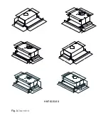
The equipment will be mounted on the housing in
points A, B, C, D using the 4 x 40 screws supplied
with the equipment. The front panel should not be
rubbed off the housing cover when the slide set
moves. Figure 3
B
C
D
A
A
B
C
D
Figure 3
Place the plastic tube supplied with the equipment
on the exhaust pipe of the equipment. Turn the
plastic tube clockwise. Figure 4
1
2
Figure 4
Figure 5
Install the flexible aluminum pipe into the plastic
hose outlet. Install the other end of the pipe on
the tube orifice on the wall. Figure 5
A
WARNING:
Since twisting and
bending the aluminum pipe reduces
air power suction, avoid bending or
twisting the pipe.
Equipment functions
The cooker hood is used in kitchens with or
without hoses.
Using the appliance with hose;
When used with a hose, the cooker hood must
be connected to a tube that will release the air.
Prefer the shortest pipe system to lead to the
tube in order to obtain maximum efficiency from
the casing. Your product is manufactured in a form
suitable for tube use.

