background image

SAFETY PRECAUTIONS 


     GENERAL GUIDELINES


1.  

Always use the manufacturer’s replacement safety 
components. The critical safety components  marked 

with 

 on the schematics diagrams should not be 

by other substitutes. Other substitute may create the 
electrical shock , fire or other hazards. Take 
attention to replace the spacers with the originals. 
Furthermore where a short circuit has occurred , 
replace those components that indicate evidence of 
overheating. 


2.  

After servicing , see that all the protective devices 
such as insulation barriers, insulation papers, shields 
and isolation R-C combinations are correctly 
installed. 


3.  

When the receiver is not being used for a long time 
of period of time , unplug the power cord of the 
Adaptor from the AC outlet. 


Color TFT LCD Module is very sensitive 
both electrically and physically.Users, 
therefore, are requested to follow the 
“Guidance of handling color TFT LCD 
Module”on the followings.


1

 - 

Be careful not to make scratch on the 
polarizer. 

Surface of polarizer is soft and can be physically 

damaged easily. 

Please do not touch, push or rub polarizer surface 

with materials over HB hardness. 


2 -


Keep clean the surface.  

Please wear rubber glove when touch the surface of 

LCD screen. Please use soft and anti-static material 
as cleaner. 


3 -


Keep out of water. 

Water on/in the LCD may cause electrical short or 

corrosion. Please wipe out dry or water carefully


4 -


Prevent swift Temperature & 
Humidity change. 

Instantaneous temperature and/or humidity change 

can make dew or ice which cause nonconformance 
such as malfunction. 


  5            High temperature & high


humidity   

                 reduce the life-time. 

LCD is not proper to be used at high temperature 
and high humidity. Please keep specified 
temperature and humidity condition. 
 

6 -         Keep out of Corrosive Gas. 

Corrosive gas effect the polarizer and the circuit 
chemically and cause defects accordingly.    
 

7  -       Electrostatic discharge can make  

                 Damage 


There are electro-static sensitive components such 

as CMOS in LCD Module. Please earth human 
body when handle the LCD.In addition, please do 
not touch the interface connector pin with  bare.  


8 -


Do not operate for a long time under 

           the same pattern


Operating LCD for a long time under the same 
pattern can cause image persistence  and can 
damage it. Please follow following guidance.       
1. Turn the power off when do not use.                
2. Change the pattern periodically.  


Summary of Contents for LM CHASSIS

Page 1: ...SERVICE MANUAL LM CHASSIS ...

Page 2: ... 4 Features 5 Inputs Outputs Diagram 6 Remote Control 7 Set Apperance 8 Service Adjustments 9 Block Diagram 12 Power Supply Diagram 13 Data Sheet VCT4993 14 Data Sheet MST6181 16 Data Sheet MTV512 24 Data Sheet TVP5150A 26 Parts List 32 Circuit Diagram Attached ...

Page 3: ...rub polarizer surface with materials over HB hardness 2 Keep clean the surface Please wear rubber glove when touch the surface of LCD screen Please use soft and anti static material as cleaner 3 Keep out of water Water on in the LCD may cause electrical short or corrosion Please wipe out dry or water carefully 4 Prevent swift Temperature Humidity change Instantaneous temperature and or humiditycha...

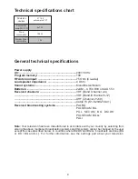
Page 4: ...ting systems PAL BG PAL SECAM BG PAL SECAM BG DK DK PAL SECAM BG LL PAL I 27 16 9 active matrix TFT 2x7 W 120 W 1 W Picture tube size type Sound outlet power 10 THD Power consumption Stand by Power consumption Note Your television has been manufactured in accordance with your country by selecting from among the above mentioned broadcasting systems and this system cannot be changed by the user exce...

Page 5: ...ff Graphic equalizer The feature of sharpness in Colour Transitions CTI Sharpness feature and picture resolution LTI in the black white transitions A clear Picture made possible by the Digital Comb Filter On screen viewing of all settings program numbers and all the processes Manual Fine Tuning 100 Program memory Infrared Remote Control equipped all the functions Child Lock Feature of viewing the ...

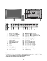
Page 6: ... the picture quality of one another RGB offers the best picture quality over the Scart 6 1 Standby status indicator 2 Network power on off button 3 Remote control receiver 4 Volume turn down button 5 Volume enhancement button 6 Menu Button 7 Source selection 8 Program decrease button 9 Program increase button 10 Speaker 11 Scart 1 12 Scart 2 13 Power supply input 14 Headphones output 15 S VHS conn...

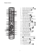
Page 7: ...ton Menu 13 Confirmation OK and Temporary picture freeze button Freeze 14 Info Txt index page button 15 Downward movement button Menus 16 Txt Question Answer button Reveal 17 Red teletext button 18 Teletext page enlarge button Double 19 Blue Teletext button 20 Teletext Mix selection buttons 21 UPDATE Button Teletext time 22 Yellow teletext button 23 Stand by On Off button 24 Picture Mode selection...

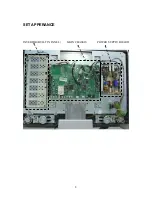
Page 8: ...8 SET APPERANCE INVERTOR BUILT IN PANEL MAIN CHASSIS POWER SUPPLY BOARD ...

Page 9: ...anish Portuguese Greek Turkish Dutch Swedish Danish Norwegian Finnish Slovenian Polish Hungarian Russian Hebrew Romanian Croatian Czech Slovak Albanian Bulgarian Macedonian Serbian B English German French Italian Spanish Portuguese Greek Turkish Dutch Swedish Danish Norwegian Finnish Slovenian Polish Hungarian Russian Romanian Croatian Czech Slovak Albanian Bulgarian Macedonian Arabic Persian PANE...

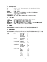
Page 10: ...ncy band VHF I AGC adjustment is 5 for this frequancy band AGC Method AGC adjustment method FIXED SYNC PW SYNC S PW PD Default SECAM MTD Secam decoding method OLD NEW default 2 5 DIMMING No adjustment will be made in this menu for service purposes Default value is 0 2 6 ADJUSTMENTS No adjustment will be made in this menu for service purposes Default values are given below VCTI BLE BLE MODE 3 BLE G...

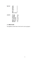
Page 11: ... 5 6CB 8 6CC 0 6CM 3 6CY 2 6CF 5 SPECTRUM 1 ADJUST R GAIN 122 G GAIN 128 B GAIN 90 R OFFSET 125 G OFFSET 125 B OFFSET 126 SUBCON 58 SUB BRI 42 2 7 EEPROM EDIT No adjustment will be made in this menu for service purposes ...

Page 12: ...der IC334 MST6181 Scart1 Analog Tuner1 TU300 Scart2 SVHS IR Key IC311 MTV512 Monitor Controller IC321 MAX9704 Audio Amp IC338 TDA7059 Headph Amp IC335 128MB DDR LVDS IC301 VGA YPrPb IC336 FRC 94XXA HDMI Analog Tuner2 TU302 IC329 Flash IC328 TxtRAM Basic Optional I2C ...

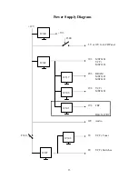
Page 13: ...iagram 12V 3V3 T300 5V or 12V for LCD Panel 3V3 MST6181 VCTi MST3383 2V5 DRAM MST3383 MST6181 1V8 VCTi MST6181 1V8 FRC Only for FRC 12V Audio T300 5V VCTi Tuner 8V VCTi Switches IC300 IC302 IC337 IC306 IC307 IC308 IC305 ...

Page 14: ... 8051 instruction set compatible CPU Up to 256 kB on chip program ROM WST PDC VPS and WSS acquisition Closed Caption and V chip acquisition Up to 10 pages on chip teletext memory Multi standard QSS IF processing with single SAW FM Radio and RDS with standard TV tuner TV sound demodulation all A2 standards all NICAM standards BTSC SAP with MNR DBX optional EIA J Baseband sound processing for loudsp...

Page 15: ...20kB XRAM 256kB Prog ROM Clock Generator Reset Test Logic I2C Master Slave 24kB Char ROM TEST RESETQ XTAL2 I2C Pxy CVBS in IFIN IFIN TAGC SIF YCbCr in CVBS out RGB in AOUT SPEAKER RGB out SVM RGB in SENSE RSW VERT EW HOUT PROT HFLB Panorama Scaler Display Deflection Processor Timer CRT PWM ADC UART Watchdog RTC I O Ports Memory Interface ADB DB PSENQ PSWEQ WRQ RDQ CPU 8051 AIN Video Frontend Color...

Page 16: ...g n Video Input Port Ÿ One RGB YUV 4 4 4 24 bit and one 4 2 2 ITU R BT 656 8 bit digital video input ports Ÿ 24 bit port supports 8 16 bit YUV 4 2 2 or 24 bit RGB YUV 4 4 4 interlaced progressive video input up to 1080i 720P n Auto Configuration Auto Detection Ÿ Auto input signal format SOG Composite Separated HSYNC VSYNC and DE and input mode all VESA IBM modes w resolution and polarity detection...

Page 17: ...MHz and up to 25 modulation n External Connection Component Ÿ Support 8051 parallel MCU bus Ÿ Supports 4 wire double data rate direct MCU bus Ÿ 32 bit data bus for external frame buffer SDR or DDR DRAM Ÿ All system clocks synthesized from a single external clock GENERAL DESCRIPTION The MST6181LDA is a high performance and fully integrated graphics processing IC solution for multi function LCD moni...

Page 18: ... 70 72 74 76 117 118 119 120 121 123 125 127 122 124 126 128 MDATA 19 MDATA 18 MDATA 17 MDATA 16 DQS 2 DQM 1 MCLKZ MVREF MCLKE MCLK 180 179 176 175 172 170 168 166 165 163 161 159 157 154 152 150 178 177 174 173 171 169 167 164 162 160 158 156 155 153 151 149 148 147 146 145 143 142 141 144 GND DQS 0 MDATA 1 MDATA 3 MDATA 5 MDATA 7 MDATA 8 VDDM MDATA 0 MDATA 2 MDATA 4 MDATA 6 MDATA 9 MDATA 10 MDAT...

Page 19: ...Bypass 42 REFP Internal ADC Top De coupling Pin 43 REFM Internal ADC Bottom De coupling Pin 44 REXT Analog Input External Resister 390 ohm to AVDD_DVI 15 HSYNC0 Schmitt Trigger Input w 5V tolerant Analog HSYNC Input from Channel 0 40 VSYNC0 Schmitt Trigger Input w 5V tolerant Analog VSYNC Input from Channel 0 41 BIN0M Analog Input Reference Ground for Analog Blue Input from Channel 0 31 BIN0P Anal...

Page 20: ...annel Green 6 DVI_G Input DVI HDMI Input Channel Green 7 DVI_B Input DVI HDMI Input Channel Blue 9 DVI_B Input DVI HDMI Input Channel Blue 10 DVI_CK Input DVI HDMI Input Clock 12 DVI_CK Input DVI HDMI Input Clock 13 Video Interface Pin Name Pin Type Function Pin VI_CKA Input w 5V tolerant Digital Video Input Clock for VI_DATA 23 0 68 VI_CKB Input w 5V tolerant Digital Video Input Clock for VI_DATA...

Page 21: ...ositive LVDS Differential Data Output 208 LVA2M Output A Link Negative LVDS Differential Data Output 207 LVA2P Output A Link Positive LVDS Differential Data Output 205 LVA3M Output A Link Negative LVDS Differential Data Output 201 LVA3P Output A Link Positive LVDS Differential Data Output 200 LVACKM Output A Link Negative LVDS Differential Data Output 205 LVACKP Output A Link Positive LVDS Differe...

Page 22: ...R SDRAM Interface 124 MCLKE Output DRAM Memory Clock Enable 125 MCLKZ Output DRAM Memory Clock Complementary Input for differential clocks 126 MCLK Output DRAM Memory Clock 127 RASZ Output Row Address Strobe active low 132 CASZ Output Column Address Strobe active low 135 WEZ Output Write Enable active low 136 DQM 1 0 Output Data Mask Byte Enable 121 153 DQS 3 0 Output Data Strobe 101 120 154 173 B...

Page 23: ... 3 3V Power ADC Power 21 38 AVDD_PLL 3 3V Power PLL Power 16 AVDD_PLL2 3 3V Power PLL Power 129 AVDD_APLL 1 8V Power Audio PLL Power 62 AVDD_MPLL 3 3V Power PLL Power 256 VDDM 2 5V Power DDR 3 3V Power SDRAM Memory Interface Power 106 122 133 145 159 174 VDDP 3 3V Power Digital Output Power 47 80 183 202 222 238 VDDC 1 8V Power Digital Core Power 77 99 151 180 213 225 246 GND Ground Ground 1 2 5 1...

Page 24: ...rval Support external counters timers T0 T1 and ET2 Single double frequency clock output Two clock output ports Two external interrupts INT1 is shared with Slave IIC interrupt source Maximum 4 channels of 6 bit ADC Flash ROM code protection selection Hardware ISP In System Programming no Boot Code required Embedded Dual Ports DDCRAM 128 byte x 2 40 pin PDIP 42 pin SDIP or 44 pin PLCC QFP package G...

Page 25: ...n Default Output Value Internal Pull Up Down Pin Type Description NC 1 39 1 No connection DA0 P5 0 2 40 1 2 I O O 1 DA0 Open Drain PWM DAC output General purpose I O open drain DA1 P5 1 3 41 2 3 I O O 1 DA1 Open Drain PWM DAC output General purpose I O open drain DA2 P5 2 4 42 3 4 I O O 1 DA2 Open Drain PWM DAC output General purpose I O open drain DA3 P5 3 5 43 4 5 I O O 1 DA3 Open Drain PWM DAC ...

Page 26: ...l RTC output is generated for synchronizing downstream video encoders Complementary 4 line adaptive comb filtering is available for both the luma and chroma data paths to reduce both cross luma and cross chroma artifacts a chroma trap filter is also available Video characteristics including hue contrast brightness saturation and sharpness may be programmed using the industry standard I2C serial in...

Page 27: ...Sliced VBI data during horizontal blanking or active video VBI modes supported Teletext NABTS WST Closed caption decode with FIFO and extended data services EDS Wide screen signaling video program system CGMS vertical interval time code Gemstar 1x 2x electronic program guide compatible mode Custom configuration mode that allows the user to program the slice engine for unique VBI data signals Power...

Page 28: ...oder With Macrovision Detection YPbPr RGB Inputs 5 Line Comb Filter and SCART Digital RGB Overlay SupportDecoder With Robust Sync Detector Literature Number SLES084 1 5 Ordering Information TA PACKAGED DEVICES PACKAGE OPTION TA 32TQFP PBS PACKAGE OPTION 0 C to 70 C TVP5150APBS Tray 0 C to 70 C TVP5150APBSR Tape and reel 0 C to 70 C TVP5150AM1PBS Tray 0 C to 70 C TVP5150AM1PBSR Tape and reel 0 C to...

Page 29: ...8 BIT 4 2 2 VBI DATA SLICER HOST PROCESSOR XTAL1 XTAL2 PCLK SCLK LINE AND CHROMA PLLS FID GLCO VSYNC PALI INTERQ GPCL VBLK HSYNC SYNC PROCESSOR SCL SDA Y C SEPARATION CHROMINANCE PROCESSING LUMINANCE PROCESSING MACROVISION DETECTION I2C INTERFACE AVID PDN Figure 1 1 Functional Block Diagram ...

Page 30: ...ound AIP1A 1 A1 I Analog input Connect to the video analog input via 0 1 µF capacitor The maximum input range is 0 0 75 VPP and may require an attenuator to reduce the input amplitude to the desired level If not used connect to AGND via 0 1 µF capacitor Refer to Figure 5 1 AIP1B 2 B1 I Analog input Connect to the video analog input via 0 1 µF capacitor The maximum input range is 0 0 75 VPP and may...

Page 31: ...BLK Vertical blank output In this mode the GPCL terminal indicates the vertical blanking interval of the output video The beginning and end times of this signal are programmable via I2C IO_DVDD 10 G2 I Digital supply Connect to 3 3 V PCLK SCLK 9 G1 O System clock at either 1x or 2x the frequency of the pixel clock PDN 28 A5 I Power down terminal active low Puts the decoder in standby mode Preserve...

Page 32: ... 294685R CC CHIP 1UF K 25V X7R 0805 C410 294121R CC CHIP 100NF J 50V 0603 NPO C331 295114R CC CHIP 1UF K 10V 0603 X5R C411 294121R CC CHIP 100NF J 50V 0603 NPO C332 295114R CC CHIP 1UF K 10V 0603 X5R C412 294121R CC CHIP 100NF J 50V 0603 NPO C333 295114R CC CHIP 1UF K 10V 0603 X5R C413 294121R CC CHIP 100NF J 50V 0603 NPO C334 295114R CC CHIP 1UF K 10V 0603 X5R C414 294121R CC CHIP 100NF J 50V 060...

Page 33: ...R 5 C538 290159R CC CHIP 15PF J 50V 0603 NPO C674 251225R EC 22UF 16V 11 5 R 5 C541 294121R CC CHIP 100NF J 50V 0603 NPO C675 251225R EC 22UF 16V 11 5 R 5 C542 294685R CC CHIP 1UF K 25V X7R 0805 C676 251225R EC 22UF 16V 11 5 R 5 C543 293113R CC CHIP 10NF K 50V 0603 X7R C677 251225R EC 22UF 16V 11 5 R 5 C544 293113R CC CHIP 10NF K 50V 0603 X7R C678 251225R EC 22UF 16V 11 5 R 5 C545 294685R CC CHIP ...

Page 34: ...124 173100R RC CHIP 10K J 1 10W 0603 IC335 453530R IC CHIP HY5DU283222BFP 33 FBGA SDRAM R231 170474R RC CHIP 47R J 1 16W 0603 TAPE IC337 453073R IC CHIP KF25BDT T R R232 170754R RC CHIP 75R J 1 16W 0603 IC338 453528R IC CHIP TDA7053AT SO16 2 0 5W ST AMP R300 172473R RC CHIP 4 7K J 1 10W 0603 COILS R301 183100R RM CHIP 10K 1 1 16W 0603 L107 053725R COIL CHIP 10UH 20 0805 R302 172473R RC CHIP 4 7K J...

Page 35: ...J 1 16W 0603 TAPE R394 172104R RC CHIP 1K J 1 16W 0603 R480 171107R RC CHIP 100R J 1 16W 0603 R395 172104R RC CHIP 1K J 1 16W 0603 R481 171107R RC CHIP 100R J 1 16W 0603 R396 172104R RC CHIP 1K J 1 16W 0603 R482 171107R RC CHIP 100R J 1 16W 0603 R397 172104R RC CHIP 1K J 1 16W 0603 R483 171107R RC CHIP 100R J 1 16W 0603 R398 172104R RC CHIP 1K J 1 16W 0603 R484 173478R RC CHIP 47K J 1 16W 0603 TAP...

Page 36: ...03 R587 171107R RC CHIP 100R J 1 16W 0603 R756 171154R RC CHIP 150R J 1 16W 0603 R588 171107R RC CHIP 100R J 1 16W 0603 R757 171154R RC CHIP 150R J 1 16W 0603 R589 171107R RC CHIP 100R J 1 16W 0603 R758 171154R RC CHIP 150R J 1 16W 0603 R590 171107R RC CHIP 100R J 1 16W 0603 R759 171154R RC CHIP 150R J 1 16W 0603 R591 171107R RC CHIP 100R J 1 16W 0603 R760 173183R RC CHIP 18K J 1 16W 0603 TAPE R59...

Page 37: ...YC16 T329 401192R TRN CHIP BC846BLT1 G SOT23 S 8 RA328 170228R RC CHIP ARRAY 4 22R YC16 MISCELLANEOUS RA329 170228R RC CHIP ARRAY 4 22R YC16 MENU 010844R TACT SWITCH 2 LEG MTSB RA330 170228R RC CHIP ARRAY 4 22R YC16 P 010844R TACT SWITCH 2 LEG MTSB RA331 170228R RC CHIP ARRAY 4 22R YC16 P 010844R TACT SWITCH 2 LEG MTSB RA332 170228R RC CHIP ARRAY 4 22R YC16 V 010844R TACT SWITCH 2 LEG MTSB RA333 1...

Reviews: