background image

Operator’s & 

Service manual

Model 6110

Digital audio lay-off
recorder

Version 1.0

BEL (Digital Audio) Ltd. 

Invicta Works  Elliott Road  Bromley  Kent  BR2 9NT UK

Tel: +44 (0)20 8460 7299  Fax: +44 (0)20 8460 0499

Email: sales@michael-stevens.com  

Web: www.bel-digital.com

Summary of Contents for 6110

Page 1: ... Model 6110 Digital audio lay off recorder Version 1 0 BEL Digital Audio Ltd Invicta Works Elliott Road Bromley Kent BR2 9NT UK Tel 44 0 20 8460 7299 Fax 44 0 20 8460 0499 Email sales michael stevens com Web www bel digital com ...

Page 2: ...des for more comprehensive control via an RS422 serial link and allows various operating parameters to be adjusted These settings are retained on power down This version has further enhancements to the AES digital audio synchronisation facilities enabling the digital output to be referenced to AES video or word clock sources ...

Page 3: ...MC 9 b Cue up with DATA and Pre roll 9 c Transport commands 9 Striping 9 LCD Display 10 DIGITAL AUDIO INPUT OUTPUT 11 Digital Referencing 11 POWER UP 11 CONNECTIONS 12 EMC COMPLIANCE 12 REMOTE CONTROL CONNECTOR 13 MEMORY ADDITION 14 POWER ON RESET 14 SPECIFICATION 15 6110 RS422 IMPLEMENTATION LIST 16 DETAIL OF SWITCHES ON FRONT FIGURE 2 17 DETAIL OF DEFAULT LCD FIGURE 3 17 REAR PANEL VIEW FIGURE 4...

Page 4: ...REAR PANEL LAYOUT 19 BLOCK DIAGRAM 20 TROUBLESHOOTING 21 APPLICATION NOTES 22 Introduction 23 Typical Applications 24 SERVICING INFORMATION CONTENTS 26 4 ...

Page 5: ...e duplicated on a remote control unit Serial control RS422 is programmable from the set up menu OPERATION AND FRONT PANEL CONTROLS There are six front panel controls From left to right these are INPUT SENSITIVITY This control permits the amplitude of the signal entering the unit to be adjusted For unity gain set this control to the centre position For other settings with audio and running time cod...

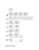
Page 6: ...e stored audio from the start of the most recent recording Whilst in ÒPlayÓ mode incoming time code is ignored A second press of ÒPlayÓ returns the unit to the Follow mode PLAY SWITCH IN SERIAL MODE Pressing ÒPlayÓ whilst in serial mode retrieves the stored audio information starting at the displayed time Pressing a second time will stop this process SET AND PAGE KEYS Refer to the diagrams 1 and 2...

Page 7: ...DIAGRAM 1 SET UP MENUS 7 ...

Page 8: ...DIAGRAM 2 SET UP MENUS 8 ...

Page 9: ...es not exactly mimic this tape recorder In particular the BEL 6110 is a purely electronic device as such it is not subject to the inertial effects invariably present in any mechanical tape recorder To the user the response of the BEL 6110 appears to be instant The main differences in operation can be summarised as follows a Jog Shuttle and DMC Each time a request to move one frame in either direct...

Page 10: ... and the current status of the unit Record Unit in record mode recording audio and time code follow mode Stop No readable code Play Unlocked replay of audio Locked Ü Reading time code before stored audio Ý Reading time code after stored audio 5 5 seconds before the audio store is full 10 Unit locked to time code in replay ...

Page 11: ...to the external AES signal connected to the AES REF digital input 48kHz 3 Word The BEL 6110 locks to the external word signal connected to the word input 48kHz TTL levels 4 Video The BEL 6110 locks to the external video signal PAL or NTSC auto select connected to the video input 1V Pk Pk 5 Internal The BEL 6110 locks to the internal crystal oscillation 48kHz 25ppm POWER UP On power up the LCD will...

Page 12: ...gital Ref Word 50 BNC 4k7 Digital Ref Video 75 BNC medium impedance 75 termination link internal Digital Output AES EBU male XLR 3 pin 110 Digital Input AES EBU female XLR 3 pin 110 Digital Ref AES 48kHz female XLR 3 pin 110 Left and Right Audio Outputs 3 pin XLR type connector male Balanced Pin 2 hot Left and Right Audio Inputs 3 pin XLR type connectors female Balanced Pin 2 hot EMC COMPLIANCE Th...

Page 13: ... CONTROL CONNECTOR The pin assignment on the 9 pin miniature D type connector is as follows Pin Function 1 Record Switch 2 Play Switch 3 Record LED 4 Ahead LED 5 Behind LED 6 5V 7 Ground 8 Ground 9 Chassis 13 ...

Page 14: ...ALL banks 0 3 and replace U22 with H Eprom and U23 with L Eprom To access CPU printed circuit board remove power IEC connection and then remove cover 19 off pozi type screws see Printed Circuit Board layout drawing in service section POWER ON RESET To reset the BEL 6110 to default settings proceed as follows Power unit off Power unit on and while the LCD display is showing the ÒLOGONÓ message Mode...

Page 15: ...onically balanced 50W Max drive capability 22dBu factory set for 18dBu Digital I O Input AES EBU 32 48kHz nominally 48kHz Output AES EBU 48kHz Reference 1 Internal crystal 48kHz 2 Audio Input Locks to AES Input frequency 3 External AES EBU 48kHz 4 External Word Clock 48kHz TTL 5 External video PAL NTSC auto select 1Vpk pk RS422 serial port 38 4 kbaud 8 data bits 1 stop bit no parity SONY protocol ...

Page 16: ...54 Anti Clog Timer Disable 20 55 Anti Clog Timer Enable 20 60 Full EE Off 20 61 Full EE Off 20 64 Edit Off 20 65 Edit On 44 04 Time Code Preset 44 05 U Bit Preset 40 10 In Entry 40 11 Out Entry 41 30 Edit Preset 44 31 Pre Roll Time Preset 44 32 Tape Audio Select 41 33 Servo Ref Select 41 34 Head Select 41 35 Colour Frame Select 41 36 Timer Mode Select 61 0A TC Gen Data Sense 61 0C Current Time Sen...

Page 17: ...DETAIL OF SWITCHES ON FRONT DEFAULT LCD REAR PANEL VIEW 17 Figure 2 Figure 3 Figure 4 ...

Page 18: ...FRONT PANEL LAYOUT 18 Audio Store Memory Options Maximum in Stereo Standard 42 24 Secs 8 Mbyte Option 1 84 48 Secs 16 Mbyte Option 2 168 96 Secs 32 Mbyte ...

Page 19: ...REAR PANEL LAYOUT 19 ...

Page 20: ...BLOCK DIAGRAM 20 ...

Page 21: ...acement PCBÕs Fault Causes Action ÔDeadÕ unit Power supply Check fuses in the IEC and supply connector then fault PCB check fuses connectors on the power supply Only fan or Power supply Check fuses on the power supply PCB backlight on fault No record In follow mode Check if in follow mode there is valid timecode at with no timecode input on rear panel timecode input No audio output No recording Ch...

Page 22: ...BEL 6110 Lay off recorder Application Notes 22 ...

Page 23: ...ion of the Bel 6000 is to think of it as a 3 track tape recorder such as the Nagra T which it has largely replaced as a Òlay offÓ recorder in VT editing which records audio signals in solid state memory rather than tape with two tracks for audio and the third for timecode The Bel 6110 is the latest CE marked version of the widely used ÒBel BoxÓ The principle of laying off audio with the Bel 6110 i...

Page 24: ...nto ÒRecordÓ at the appropriate time whilst monitoring the Master VTR The Master VTR is stopped at the end of the required section together with the Bel 6110 The Bel 6110 will then drop into the ÒPlay ReadyÓ mode ready for the VTR to be rewound The recording may be checked if required by pressing the ÒPlayÓ button Whenever the Master VTR plays back the relevant section the Bel 6110 will replay the...

Page 25: ...he installed memory 42 84 or 168 Secs in stereo The ÒwindowÓ provided by the Bel 6110 can be recorded and replayed in the same way as magnetic tape If recording is attempted outside of this window then no recording will take place and no record flags will be returned by the equipment Figure 3 The Bel 6110 is not only an editing tool but may also be used for audio dubbing for example in the making ...

Page 26: ...SERVICING INFORMATION CONTENTS Preset resistors 27 Preset capacitors 27 To remove CPU and ADAREF printed circuit boards 28 To Remove power supply 29 26 ...

Page 27: ...just RV5 for 17dB across Right output connector across 600 load Adjust RV6 for 17dB across Left output connector across 600 load Set sensitivity control on the front panel for 6dB across 600 loads on the output connectors and check for channel balance Trim RV8 and RV9 as necessary Check for 6dB across 600 loads on the output connectors when in ÒrecordÓ E E and channel balance Trim RV3 or RV4 if ne...

Page 28: ...d circuit boards cut the cable tie holding the ADAREF power cable on the underside of the ÔCPUÕ printed circuit board and pull ADAREF board away from CPU board disconnecting PLI SKI and PL2 SK2 9 To re assemble follow the above in reverse order firstly pushing the CPU and ADAREF boards together and fitting a cable tie holding the ADAREF power cable in position NOTE Care should be taken not to trap...

Page 29: ...4 3 on the chassis side and 1 on the underside of chassis see drawing 2 Disconnect all connectors from the power supply printed circuit board PL1 PL5 5 off 3 Tilt power supply towards the chassis side and lift out 4 Re assemble in reverse order making sure the spacer under the power supply chassis heat sink is properly located see drawing 29 ...

Reviews: