background image

Installation and User Guide

BM-A2-64MADI

MADI Audio and Status Monitor

64MADI

MENU

MADI DATA

PSU 1

2

L

R

VOLUME

BALANCE

CHANNEL PAIR 

SELECT

CHANNEL PAIR 

MADI AUDIO AND DATA MONITOR 

MAX

MIN

LEFT

RIGHT

PUSH TO CENTRE

PUSH TO MUTE

0

-10

-20

-30

-40

-50

-60

PUSH TO SELECT

HEADPHONES

Valid Audio


0


-6


-12


-18


-24


-36


1


2


3

4

5


6


7

8

9


10


11 12

13


14


15 16

17


18


19 20

21


22


23 24

25


26


27 28

29


30


31 32

Ch Pair 

Summary of Contents for BM-A2-64MADI

Page 1: ...Installation and User Guide BM A2 64MADI MADI Audio and Status Monitor 64MADI MADI DATA PSU 1 2 MADI HEADPHONES Valid Audio 0 6 12 18 24 36 1 2 3 4 5 6 7 8 9 10 11 12 Ch Pair ...

Page 2: ...cled in a manner that protects human health and the environment For more information about where you can drop off your waste equipment for recycling please contact your local city office your household waste disposal service or where you purchased the product User s Notice and disclaimer No part of this manual may be reproduced transmitted transcribed stored in a database system or translated with...

Page 3: ...ERNET Port 10 Setting Up Operation 11 Block Diagram 11 Front Panel Operation 12 Selecting a channel to monitor 12 Volume Control 12 Balance Control 12 Using the MENU encoder 13 Main Configuration Display 13 Synchronisation 13 Synchronisation frequency display 14 Sample Rate Converters SRCs 14 MADI input source selection 14 MADI input mode selection 14 MONO mode selection 15 Appendix 18 MADI Flags ...

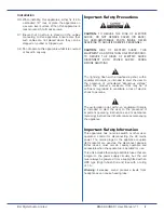
Page 4: ...apparatus There are no user replaceable fuses 19 An external over current protection device is required to protect the wiring to this apparatus This protection device must be installed according to current wiring regulations In certain countries this function is supplied by use of a fused plug 20 If an extension power cable or adaptor is used ensure that the total power rating of the power cable a...

Page 5: ...rrowhead symbol within equilateral triangle is intended to alert the user to the presence of uninsulated dangerous voltage within the product s enclosure that may be of sufficient magnitude to constitute a risk of electric shock to persons The exclamation point within an equilateral triangle is intended to alert the user to the presence of important operating instructions and maintenance servicing...

Page 6: ... humidity RH are as follows Temperature 5ºC to 40ºC RH Operating 20 to 80 What s In The Box Unpacking Unpack the BM A2 64MADI with care It is always a good idea to store all packaging if practical in case you ever need to return the unit to Bel for any reason The shipping carton should contain the items listed below Please contact your distributor immediately if any of them are missing or damaged ...

Page 7: ... speakers and outputs Balance Rotary encoder with push action to control the monitor balance of the selected channel pair Pressing the encoder will centre the audio output Channel Pair L R meters Hi resolution 52 segment tri colour LED bargraph meters with peak hold Meters follow the Channel Pair Select control 4 Speakers Two high quality high output full range speakers to present the selected aud...

Page 8: ...AES UNBALANCED OUTPUTS 37 way female Dsub connector providing unbalanced AES3 id outputs of all available MADI channels OUT Optical MADI output SC connector IN Optical MADI input SC connector ETHERNET Ethernet port RJ45 REF IN External synchronisation reference input BNC WK OUT Derived wordclock output from selected reference input BNC AES OUT Derived AES3 sync output from selected reference input...

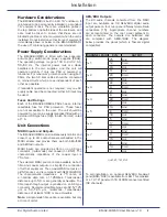
Page 9: ...ange is 100 to 240 V AC 50 60 Hz The internal power rails are diode paralleled to the two supplies and the unit will operate normally if only one PSU is powered or functional For maximum protection when using both PSUs the two AC inlet cables should be connected to mains circuits which are as independent of each other as possible If redundant operation is not required only one AC supply cable need...

Page 10: ...ar panel 37 way female Dsub connector 16 The outputs are unbalanced AES3 id but are compliant with AES3 1992 in all other respects The table below provides the pinout PIN OUTPUT AUDIO CHANNELS 1 AES 1 Chs 1 2 2 AES 2 Chs 3 4 3 AES 5 Chs 9 10 4 AES 6 Chs 11 12 5 AES 9 Chs 1 2 6 AES10 Chs 3 4 7 AES 13 Chs 9 10 8 AES 14 Chs 11 12 9 AES 17 Chs 1 2 10 AES 18 Chs 3 4 11 AES 21 Chs 9 10 12 AES 22 Chs 11 ...

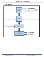
Page 11: ...bypass Sync References Inputs Outputs Bargraph and status displays Input source select via LCD Sync source select via LCD SRC enable via LCD AES3 id Outputs AES EBU Outputs AES interface MADI input coax MADI Loop through output fibre MADI Loop through output coax L R speaker outputs Headphone output TRS jack L R line outputs 2 x XLR3M Setting Up Operation ...

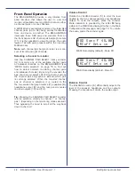
Page 12: ... turning the encoder the blue channel pair select LED 12 will scroll across the channel pair bargraphs to indicate which pair is currently selected When the required channel pair or channel is selected it is routed to the the hi resolution bargraph meters 7 speakers 8 headphone output 9 and the rear panel mounted line level outputs 13 and 14 Tip Pressing the CHANNEL PAIR SELECT encoder returns sel...

Page 13: ... icon will appear on the display and this points to the parameter that can be changed Synchronisation TheBM A2 64MADIshouldnormallybeusedasaslave device synchronised to an external clock reference BM A2 64MADI offers a choice of synchronisation sources The selected source is also used as reference for sample rate converters if enabled thus ALL audio outputs both in AES EBU and AES3 id formats will...

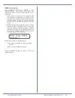
Page 14: ...and the nature of the transfer process Note Passing Dolby encoded material through sample rate converters will corrupt the Dolby bitstream Press the Menu encoder again to move the pointer to the SRC section Note This function is to synchronise the incoming MADI source to a local clock The sample rate would remain the same MAD Sync F 48 00 SRCoff Opto in Rotate the encoder to select between SRCoff ...

Page 15: ...enables the user to scroll through and monitor each of the AES channel pairs 1 to 32 in turn MONO changes the monitoring mode to single channel selection Turning the same encoder now only increments the channel count by 1 enabling individual channels within the MADI stream to be monitored The display indicates which channel is currently selected for monitoring MONO Mode MONO Channel 1 Rotate the e...

Page 16: ...l pair The bits increment from right to left So Bit 0 is on the right and bit 31 is on the left Audio data is represented by the two dots in the middle of the data sequence Audio data can be interrogated in MADI Audio data pages 31 28 29 30 31 30 29 28 27 26 25 24 23 22 21 20 19 18 17 16 15 14 13 12 11 10 9 8 7 6 5 4 3 2 1 0 0 1 2 3 LSB MSB Audio data MADI frame synchronisation bit When set to 1 t...

Page 17: ...it Within the display A1L contains the lower 12 bits of the audio and A1H contains the upper 12 bits There are two MADI Audio pages for the selected channel pair The first A1H and A1L represents the left channel and the second page A2H and A2L represents the right channel Use the MENU encoder 2 to scroll between these pages AES Channel Status Bytes Six of the most commonly used Channel Status byte...

Page 18: ...ates 0 0 0 Emphasis not indicated Receiver defaults to no emphasis with manual override enabled 0 0 1 No emphasis Receiver manual override is disabled 0 1 1 50 μs 15 μs emphasis see ITU R BS 450 Receiver manual override is disabled 1 1 1 ITU T J 17 emphasis with 6 5 dB insertion loss at 800 Hz Receiver manual override is disabled All other states of bits 2 to 4 are reserved and are not to be used ...

Page 19: ... not double the rate indicated in byte 4 if that is used Manual override is disabled 1 0 0 1 Single channel double sampling frequency mode stereo mode right Subframes 1 and 2 carry successive samples of the same signal The sampling frequency of the signal is double the frame rate and is double the sampling frequency indicated in byte 0 but not double the rate indicated in byte 4 if that is used Ma...

Page 20: ...s 24 bits as indicated by bits 0 to 2 above Audio sample word length if maximum length is 20 bits as indicated by bits 0 to 2 above States 0 0 0 Word length not indicated default Word length not indicated default 1 0 0 23 bits 19 bits 0 1 0 22 bits 18 bits 1 1 0 21 bits 17 bits 0 0 1 20 bits 16 bits 1 0 1 24 bits 20 bits All other states of bits 3 to 5 are reserved and are not to be used until fur...

Page 21: ... is defined by bits 3 to 0 of this byte 0 1 0 Multichannel mode 2 The channel number is defined by bits 3 to 0 of this byte 0 1 1 Multichannel mode 3 The channel number is defined by bits 3 to 0 of this byte 1 1 1 User defined multichannel mode The channel number is defined by bits 3 to 0 of this byte All other states of bits 4 to 6 are reserved and are not to be used until further defined BITS 3 ...

Page 22: ...NCY States 0 0 0 0 Not indicated default 0 0 0 1 24 kHz 0 0 1 0 96 kHz 0 0 1 1 192 kHz 0 1 0 0 384 kHz 0 1 0 1 Reserved 0 1 1 0 Reserved 0 1 1 1 Reserved 1 0 0 0 Reserved for vectoring 1 0 0 1 22 05 kHz 1 0 1 0 88 2 kHz 1 0 1 1 176 4 kHz 1 1 0 0 352 8 kHz 1 1 0 1 Reserved 1 1 1 0 Reserved 1 1 1 1 User defined BIT 7 SAMPLING FREQUENCY SCALING FLAG State 0 No scaling default 1 Sampling frequency is ...

Page 23: ...formation to test valid reception of the entire channel status data block bytes 0 to 22 inclusive For serial implementations the initial condition of all ones should be used in generating the check bits with the LSB transmitted first There is no default this field shall always be coded with a correct CRCC Note Please refer to the AES standard for digital audio Digital input output interfacing Seri...

Page 24: ...to 20 kHz 1 dB SPEAKER OUTPUTS Peak accoustic level 2ft 100 dB SPL Shielding Magnetic Main amplifier Noise THD 80 dB w r t maximum output SYNCHRONISATION Sample Rate Conversion SRC available for all channels switchable Sources Word clock AES Video Black and Burst MADI Video Sync input PAL NTSC 50 60 Hz SD Word clock input 44 1 kHz to 96 kHz DC coupled positive going pulses Word clock output Follow...

Page 25: ...Bel Digital Audio Limited 3 Horwood Court Bletchley Milton Keynes MK1 1RD United Kingdom Tel 44 0 1908 641063 Email info beldigital com URL www beldigital com ...

Reviews: