background image

USER MANUAL

belfuse.com/power-solutions

LDX-B20

150 W Buffer Module

Summary of Contents for LDX-B20

Page 1: ...USER MANUAL belfuse com power solutions LDX B20 150 W Buffer Module ...

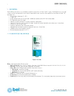
Page 2: ...y contact and an opto isolated input for inhibit Integrated safety circuit that disconnects the capacitor bank in case of internal failure Parallelable for power and backup time increase Wide operating temperature 20 C to 70 C 1 1 CONNECTORS AND USER INTERFACE Figure 1 Front View DC bus wired in parallel with the DC line to protect Mode switch button used to select the operating voltage range of t...

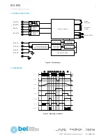
Page 3: ...itors bank S afety sw itch S tep dow n converter D C B U S D C B U S D C B U S D C B U S M icrocontroller R eady relay B ackup relay IN H IB IT IN H IB IT R E A D Y B A C K U P O vervoltage and overcurrent protection S elected S tatus LE D s M ode selection m ode Figure 2 Block diagram 1 3 OPERATION A C Line D C Line U capacitor R eady relay B ackup relay G reen LE D R ed LE D Inhibit 1 2 4 3 5 6 ...

Page 4: ...line because the inhibit input is activated The unit powers off 8 When the AC line returns the LDX B20 turns on The green LED turns on because the capacitors are already charged 9 The inhibit input is deactivated The relay ready activates and the nit is ready for buffering 10 On AC power loss the unit uses the energy stored on the capacitors to keep the DC line regulated eventually until full disc...

Page 5: ...T DATA Voltage range Nominal 12 24 48 72 VDC Auto detection Input current Max 20 A GENERAL DATA Operating modes User settable by front botton AUTO follows the SMPS Output voltage Fixed Output voltage 12 24 48 72 VDC Control CPU Operating temperature 20 C to 70 C Storage temperature 20 C to 85 C Humidity Max RH 95 non condensing Cooling Natural convection Input ground isolation 0 75 kVDC Safety sta...

Reviews: