tech.support@psbel.com
belfuse.com/power-solutions
USER MANUAL
6
3 FUNCTIONAL DESCRIPTION
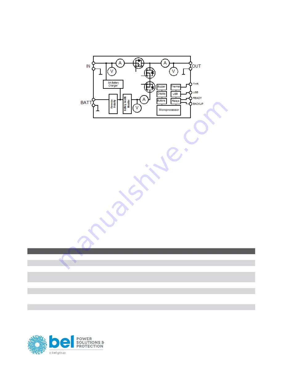
A simplified block diagram of the LDX-U20 is shown in Figure 2.
Figure 2. LDX-U20 simplified block diagram
LDX-U20 is a high performance digitally controlled DC-UPS that can be used in any DC system with a rated voltage between 12V and 28V
and up to 20A of input current.
It includes a battery charger capable of charging Lead-Acid, Ni-MH and Li-ION batteries with a rated voltage between 12V and 28V and able
to deliver a charge current up to 5A.
The input voltage is continuously monitored by the microprocessor. In case of a power outage the battery is connected to the load
instantaneously through an active switch, reducing the power loss to a minimum.
The product offers additional features to improve the performance and the reliability of the system, which are described below.
3.1 REMOTE MONITORING AND CONTROLLING
3.1.1
USB
The USB interface allows the communication with the proprietary POWERMASTER software (available for download at www.nextys.
com) which allows the full control and monitoring of the LDX-U20 unit with the ease of the PC.
3.1.2
DIGITAL INPUT
An opto-isolated input allows the inhibition of the backup function. The polarity of the input can be defined using the Inhibit polarity
setting (see §5.2.15).
3.1.3
DRY CONTACT OUTPUTS
2 relays are present on the LDX-U20. User can chose which event activates the relay and the polarity. The list of events is the following:
NAME
DESCRIPTION
DEFAULT SETTING
Backup
Active when the system is running on the batteries.
Relay 2
SoC < 25% (Low Battery)
Active when the State of Charge (SoC) of the battery is below 25%.
Unused
Battery life time expired
Active when the battery life time counter is exceeding the value specified on §5.2.13
Relay 1
Battery Ri too high
Active when the measured battery internal resistance (Ri)> alarm threshold.
The threshold is specified using setting §5.2.9 and §5.2.10.
Relay 1
Battery failure
Active when the battery could not be charged correctly.
Relay 1
Battery under voltage
Active when the battery voltage is below the value specified on §5.2.7
Unused
Battery backup time left < 25%
Active when the remaining backup time is higher than the 75% of the maximal backup
time defined on §5.2.14
Unused
PC OFF signal
Activated by the PC shutdown and automatic restart function. See §3.3 for details.
Unused
Table 1. Relays signals
By default both relays polarity is set to NC (Normal Close).


