tech.support@psbel.com
belfuse.com/power-solutions
BCD20021-G Rev AF, 29 November 2021
Page 20 of 26
X Series
375, 500 Watt AC-DC and DC-DC DIN-Rail Converters
© 2021 Bel Power Solutions & Protection
Description of Options
Single options D1, D2, D5, R
are available on the AUX1 terminal (10), referenced to Vo– or Vo2–.
Option M1
and
M2
designate a combination of several options accessible via a D-SUB connector or in some cases on the AUX1
and AUX2 terminals. Option M1 includes the function SD.
Note:
In double-output models, the options D1, D5, R, and SD concern only output 2 connected to terminals 6, 7, 8, and 9.
Single Options Using the AUX1 Pin
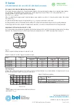
The connection is shown in the figure below. For the description refer to
Adjustment of V
o
or V
o2
(
next section).
AUX1
1
11
10
9
8
7
6
5
4
3
2
Adjustment with
V
ext
AUX1
1
11
10
9
8
7
6
5
4
3
2
Adjustment with
R
ext
Vo2+
or Vo+
Vo2–
or Vo–
R
ext1
R
ext2
V
ext
+
Vo2–
or Vo–
12
12
06160a
AUX2
AUX2
Fig. 17
Connection of adjust resistors or an external voltage source to adjust the output voltage V
o
or V
o2
(option M1 or M2 not fitted)
Multiple Options M1 or M2
The option board is suitable for applications, where several options are needed. Option M1 is standard for battery charger models,
option M2 is suitable for applications without battery or for simple applications with battery.
In general, the multiple options M1 or M2 are connected to an additional D-SUB connector. Some signals (but not option R) can
also be connected to AUX1 and AUX2, if the D-SUB connector is not suitable to the customer.
Table 15: Pin allocation of the 9 pin D-SUB connector
Pin
Designation
Description
1
GND1
1
System ground / common signal return
2
R
R input
3
3
VCC
2
Positive supply voltage (
≈
output 2)
4
D1
Output voltage monitor
V
o low D1
3
5
D5
Output 2 voltage monitor
V
o low D5
3
6
SD
Shutdown
3
7
D-adj
Adjustment of threshold values of D1 or D5
8
D2
Input voltage monitor
V
i low
9
Sys-OK
System okay (all outputs are okay)
1
Do not connect GND1 (pin 1) with the neg. output (–)
2
Do not connect VCC (pin 3) with the positive output (+)
3
In double-output models, R, D1, D5, SD concern output 2 only.


