4
INSTALLATION INSTRUCTION
tech.support@psbel.com
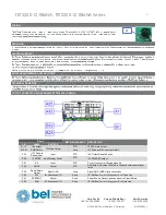
Row B
MATING SEQUENCE
DESCRIPTION
PIN
NAME
PIN TYPE
P1-12,
12V Output
12V Main Output
STD
12 VDC main output
P13-24
PWR Return
Long
12V Main and 12VSB Output return
P25
Smart
Redundant Bus
Signal
I/O
STD
Smart share for system efficiency performance
Common bus to all sharing power modules
P26
Return Sense
Analogue Input
STD
12V main output Remote Sense Return
P27
ACOK
Output
STD
Indicate AC voltage is present and within operational limits.
P28
12V Load
Share Bus
Bi-Direction
Analogue I/O
STD
12V Main Output Current Share Signal (bus)
P29
PSON
Input
STD
Active low; 12V main output on/off control
P30
PS_KILL
Input
Short
Turns power module on/off, short (MLBF) contact.
P31
No Connection
Short
No End User Connection
P32
SMB_Alert
Output
Short
Active low; I2C alert signal (interrupt)
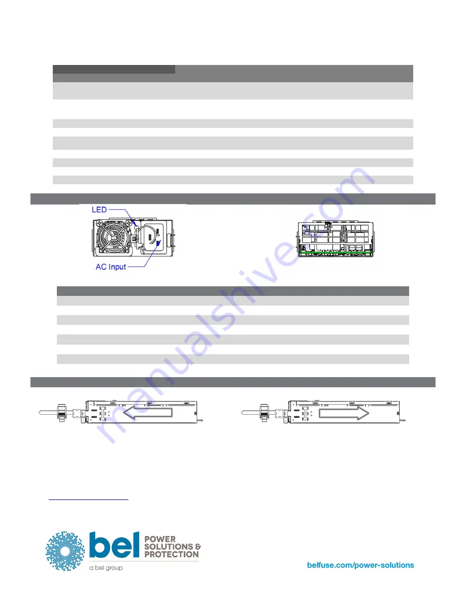
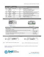
UNIT FRONT/REAR AND LED INDICATOR TET2200-12-086NA
Figure 3. Front view
Figure 4. Rear view
OPERATING CONDITION
LED State
Output ON and OK
Solid GREEN
No AC power to all power supplies
OFF
AC cord unplugged, or AC power lost; with a second power supply in parallel still with AC input power.
OFF
AC present / Only 12 VSB on (Standby mode)
0.5 Hz Blink GREEN
Sleep PS in Smart redundant state/off line mode
2 Hz Blink GREEN
Power supply critical event causing a shutdown; eg. OCP, OVP, OTP, Fan Fail
Solid AMBER
Power supply in FW upload mode
2 Hz Blink GREEN
AIRFLOW DIRECTION
Figure 1. TET2200-12-086NA Side view and Airflow direction
Figure 2. TET2200-12-086RA Side view and Airflow direction
Additional information about characteristics and application of the products is available from the Bel Power Solutions web site at
Airflow
Airflow


