background image

AIRBLADE® DRYER


Mix and Match


1MANUL011         

                    Belanger, Inc. * 1001 Doheny Ct. * Northville, MI 48167 * Ph (810) 349-7010 * Fax (810) 380-9681

                            51


Installation 

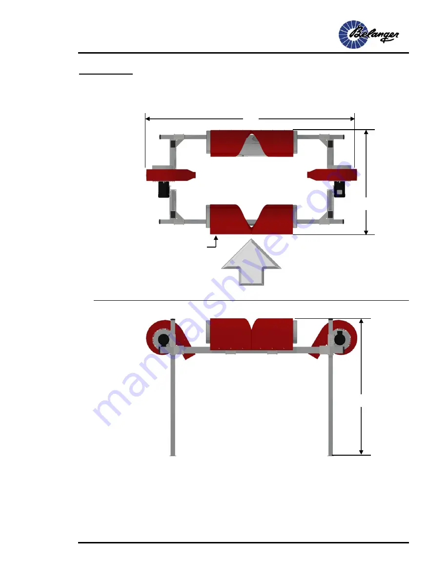
6-Nozzle System Overview: Floor Mounted 


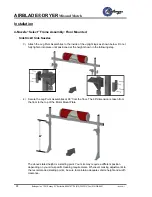
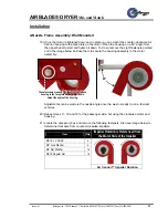
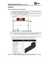
Before you begin the assembly of the AirBlade® Express frame, keep in mind that the head beam 
assembly with the housings angled 10° is on the entrance side of the bay and that the flat portions are 
facing towards the entrance also.  


122” 

166” 

10° Angled Housings 

90-1/2” 

Summary of Contents for AirBLade Mix & Match

Page 1: ...1MANUL011 REV 02 Belanger Inc P O Box 5470 Northville MI 48167 5470 Customer Service Phone 248 374 4700 Fax 248 380 9681 www belangerinc com Dryer Mix Match ...

Page 2: ......

Page 3: ... accompanying equipment are protected by United States and International copyright and patent laws You may make one copy of this manual Do not make additional copies of this manual or electronically transmit it in any form whatsoever in whole or in part without the prior written permission of Belanger Inc ...

Page 4: ......

Page 5: ... System Overview Floor Mounted 20 2 Nozzle Frame Assembly Floor Mounted 21 2 Nozzle System Overview Wall Mounted 23 2 Nozzle Frame Assembly Wall Mounted 24 4 Nozzle Select System Overview 28 4 Nozzle Select System with Air Cannons Overview Floor Mounted 30 4 Nozzle Select System with Side Kicks Overview Floor Mounted 31 4 Nozzle Select Frame Assembly Floor Mounted 32 4 Nozzle System Overview Wall ...

Page 6: ...Belanger Inc 1001 Doheny Ct Northville MI 48167 Ph 810 349 7010 Fax 810 380 9681 1MANUL011 Table of Contents Maintenance 101 Routine Procedures 101 Trouble Shooting 102 Exploded Parts View 103 Motor Maintenance Supplied by Baldor 114 ...

Page 7: ...junction with Belanger equipment will void the warranty Hydrofluoric Acid Ammonium Bi flouride Bromic Acid Muriatic Acid Sulfonic Acid Phosphoric Acid Hydrogen Cyanide Hydrochloric Acid Sodium Hydroxide and Chlorinated Solvents 5 Seller makes no warranty express or implied with respect to the design or operation of any entire system in which Seller s goods sold hereunder are mere components 6 In n...

Page 8: ... 8 Limited Warranty of the Belanger Terms and Conditions of Sales describes the potential limitation of warranty due to your chemical selection 4 This warranty shall be void for all equipment failures and premature component wear caused by the use of corrosive chemicals in the wash process The following list includes some but not all of the particularly corrosive chemicals that if used in conjunct...

Page 9: ...rds used in this manual and on warning labels tell you the seriousness of particular safety hazards The precautions that follow must be followed to prevent death injury or damage to the equipment DANGER This signal word is used to alert you to a hazard or unsafe practice which WILL RESULT IN DEATH OR SERIOUS INJURY This alerts you to a hazard or unsafe practice which COULD RESULT IN DEATH OR SERIO...

Page 10: ...quipment Doing so will prevent unexpected energization startup or release of hazardous energy while maintenance and servicing activities are being performed BE SURE TO OBSERVE OPERATING ENVELOPE EQUIPMENT MAY START UNEXPECTICALLY OVERHEAD ROTATING AND OR MOVING COMPONENTS COULD RESULT IN SERIOUS INJURY OR DEATH BE AWARE OF FOREIGN OBJECTS IN THE AREA SURROUNDING A ROTATING PIECE OF EQUIPMENT OBJEC...

Page 11: ...he AirBlade Dryer is available in various configurations The configurations are as follows AirBlade Floor Mounted AirBlade Select Floor Mounted AirBlade Express Floor Mounted AirBlade Express 180 Floor Mounted AirBlade Wall Mounted AirBlade Select Wall Mounted AirBlade Express Wall Mounted AirBlade Express 180 Wall Mounted AirBlade Select with Side Kick Option AirBlade Select with SideKick Floor M...

Page 12: ...n nozzles for the 40HP and the 60HP systems should be mounted in specific positions Levelers can be purchased at any good hardware store Home Depot This document is laid out in eight sections 2 Nozzle Wall Mount System 2 Nozzle Floor Mount System 4 Nozzle Wall Mount System 4 Nozzle Floor Mount System 6 Nozzle Wall Mount System 6 Nozzle Floor Mount System 10 Nozzle Wall Mount System 10 Nozzle Floor...

Page 13: ...t AirBlade Select Green 4 Nozzle Floor Mount AirBlade Select Orange 4 Nozzle Floor Mount AirBlade Select Red 4 Nozzle Floor Mount AirBlade Select Yellow 4 Nozzle Floor Mount AirBlade Select Gray 4 Nozzle Floor Mount Air AirBlade Select Item Description Select with Side Kicks 4 Nozzle Black 4 Nozzle Floor Mount with Side Kicks Select Blue 4 Nozzle Floor Mount with Side Kicks Select Green 4 Nozzle F...

Page 14: ...pper Mount Assembly Aluminum 2 AirBlade Lower Mount Assembly Aluminum 2 AirBlade Housing Lift Assembly 1 4 Nozzle Floor Mount with Air Cannons Powder Coated Select Description Quantity Floor Mount Frame Assembly Powder Coated 1 AirBlade Upper Mount Assembly Powder Coated 2 AirBlade Lower Mount Assembly Powder Coated 2 AirBlade Housing Lift Assembly 1 4 Nozzle Floor Mount with Side Kicks Aluminum S...

Page 15: ...m Description Quantity Floor Mount Frame Assembly Aluminum 2 AirBlade Upper Mount Assembly Aluminum 4 AirBlade Lower Mount Assembly Aluminum 2 AirBlade Housing Lift Assembly 1 10 Nozzle Floor Mount Aluminum Description Quantity Floor Mount Frame Assembly Aluminum 3 AirBlade Upper Mount Assembly Aluminum 6 AirBlade Lower Mount Assembly Aluminum 4 AirBlade Housing Lift Assembly 1 10 Nozzle Floor Mou...

Page 16: ...unt AirBlade Select Item Description 6 Nozzle Item Description 10 Nozzle Requires one 4 Nozzle and one 2 Nozzle Requires two 4 Nozzles and one 2 Nozzle 2 Nozzle Wall Mount Aluminum Description Quantity Dryer Wall Mount Assembly Aluminum 1 AirBlade Upper Mount Assembly Aluminum 2 AirBlade Housing Lift Assembly 1 2 Nozzle Wall Mount Powder Coated Description Quantity Dryer Wall Mount Assembly Powder...

Page 17: ...ed w high sides 1 Dryer Wall Mount Assembly Powder Coated 1 AirBlade Upper Mount Assembly Powder Coated 4 AirBlade Lower Mount Assembly Powder Coated 2 AirBlade Housing Lift Assembly 1 10 Nozzle Wall Mount Aluminum Description Quantity Dryer Wall Mount Assembly Aluminum 1 Dryer Wall Mount Assembly Aluminum w high sides 2 AirBlade Upper Mount Assembly Aluminum 6 AirBlade Lower Mount Assembly Alumin...

Page 18: ...and inspect shipment for damage and to verify that all pieces are there If there is any damaged equipment file a claim with the trucking company immediately Receiving party is responsible for filing claim with trucking company Notify your local distributor or Belanger Inc immediately If shipment is determined damaged or incomplete CAUTION It is recommended that a licensed electrician is contracted...

Page 19: ...el space required 52 1 4 Unit height overall 122 Unit height overall 122 Unit width overall 166 Unit width 166 min 204 1 2 max AirBlade Select with Side Kicks 40 HP Floor Mounted Tunnel space required 55 1 2 Unit height overall 122 Unit width overall 170 AirBlade Express 60 HP Floor Mounted AirBlade Express 60 HP Wall Mounted Tunnel space required 90 1 2 Tunnel space required 90 1 2 Unit height ov...

Page 20: ...129 32 2 208 60 3 112 28 230 60 3 56 14 460 60 3 68 17 380 50 3 64 16 415 50 3 AIRBLADE DRYER SELECT with AIR CANNONS 40 HP 44 11 575 60 3 129 32 2 208 60 3 112 28 230 60 3 56 14 460 60 3 68 17 380 50 3 64 16 415 50 3 AIRBLADE DRYER SELECT with SIDE KICKS 40 HP 44 11 575 60 3 193 32 2 208 60 3 168 28 230 60 3 84 14 460 60 3 102 17 380 50 3 96 16 415 50 3 AIRBLADE DRYER EXPRESS 60HP 66 11 575 60 3 ...

Page 21: ... enough for one AirBlade Dryer wall mount only If you have multiple AirBlade Dryer s that need to be wall mounted multiply the given quantities by the number of AirBlade Dryers you have purchased The threaded rods are to mount through the wall at the 3 points given on the wall mount bracket Each threaded rod will have one backing plate two stainless nuts one stainless steel lock washer and two sta...

Page 22: ...tors If you do not have any head beam covers then please move on to the next section 1 Pop open the top of the 6 white plastic caps Remove the fasteners washers and head beam cover from each head beam Place the parts where they will not get misplaced Note If you have multiple head beam covers you may want mark the inside of the head beam covers so that they are placed back on to their correct head...

Page 23: ...Note Before you begin the assembly of the AirBlade frame be sure that the flat portions of the AirBlade housings are toward the exit of the bay as indicated by the arrow in the image below The following is important in understanding how to determine Impeller rotation Impeller Rotation is Referenced from the Motor Side of the Impeller AirBlade Impeller Rotation ...

Page 24: ...AIRBLADE DRYER Mix and Match 20 Belanger Inc 1001 Doheny Ct Northville MI 48167 Ph 810 349 7010 Fax 810 380 9681 1MANUL011 Installation 2 Nozzle System Overview Floor Mounted 122 164 36 1 8 ...

Page 25: ...ipped on Clamp the head beam assembly to the forks of the forklift and position it in its tunnel location 3 Lift it until there is a 91 clearance from the bottom surface of the head beam to the floor 4 Slide one of the clamp assemblies and one of the legs into place as shown below but do not tighten the bolts until the height is set and the frame has been leveled Be sure the base of the legs face ...

Page 26: ...legs have been attached to the head beam space them as shown in the image below Note 45 dimension is taken from the outside of the driver side leg to the inside of the passenger side Guide Rail Actual tunnel depth will vary according to available building space 7 Once the component is properly placed leveled in all directions and the legs are squared you can tighten all of the fasteners and lag th...

Page 27: ...LADE DRYER Mix and Match 1MANUL011 Belanger Inc 1001 Doheny Ct Northville MI 48167 Ph 810 349 7010 Fax 810 380 9681 23 Installation 2 Nozzle System Overview Wall Mounted 122 166 min 204 1 2 max 23 3 4 Floor ...

Page 28: ...lamp Pieces 2 Wall Mount Bracket Weldment 2 Clamp Cap Half 2 1 2 Stainless Steel Lock Washers 6 1 2 13 x 5 1 2 Stainless Steel Bolts 6 2 Locate the skid that the AirBlade Dryer head beam assembly shipped on Using the forklift spread the forks as far as they will go Center the forklift to the head beam and lift up underneath the head beam just until the forks are touching the bottom of the head bea...

Page 29: ...t this time you can tighten both of the center rods completely 7 Mark and drill through the wall for the other hole in the wall mount bracket and tighten the rods down completely 8 Place the level on the other end of the head beam level it out verify the 91 dimension from the floor to the bottom of the head beam and fasten the second wall mount bracket to the wall using the same guidelines you use...

Page 30: ...racket you can side shift the head beam in that direction 12 If the distance is greater you will have to loosen the AirBlade housing brackets and slide them over using the supplied housing lift assembly by following the steps below Note If you need to shift the AirBlade housings to the left start with the left housing since there is only one Lift Assembly supplied Locate the supplied Housing Lift ...

Page 31: ... as shown below Move the housing to the appropriate location Retighten the AirBlade Housing Bracket and remove the Housing Lift Assembly Repeat these steps on the other housing When completed remove the Housing Lift Assembly replace the fasteners and store the Lift Assembly for future use 13 Once the housings are centered to the door you can tighten the fasteners that attach the head beam to the w...

Page 32: ...1 1MANUL011 Installation 4 Nozzle Select System Overview Note Before you begin the assembly of the AirBlade Select frame be sure that the flat portions of the AirBlade housings are toward the exit of the bay as indicated by the arrow in the image below Select System with Air Cannons Select System with Side Kicks ...

Page 33: ... in understanding how to determine Impeller rotation Impeller Rotation is Referenced from the Motor Side of the Impeller Impeller Rotation is Referenced from the Motor Side of the Impeller AirBlade Impeller Rotation Air Cannon Impeller Rotation Impeller Rotation is Referenced from the Motor Side of the Impeller Passenger Side Clockwise Driver Side Counter Clockwise Side Kick Impeller Rotation ...

Page 34: ...r Inc 1001 Doheny Ct Northville MI 48167 Ph 810 349 7010 Fax 810 380 9681 1MANUL011 Installation 4 Nozzle Select System with Air Cannons Overview Floor Mounted 122 166 58 9 16 This dimension will vary slightly depending on the nozzle angles ...

Page 35: ...ille MI 48167 Ph 810 349 7010 Fax 810 380 9681 31 Installation 4 Nozzle Select System with Side Kicks Overview Floor Mounted 122 177 5 16 51 3 16 This dimension will vary slightly depending on the nozzle angles This dimension will vary slightly depending on the nozzle angles ...

Page 36: ...assembly shipped on Clamp the head beam assembly to the forks of the forklift and position it in its tunnel location 3 Lift it until there is a 91 clearance from the bottom surface of the head beam to the floor 4 Slide one of the clamp assemblies and one of the legs into place as shown below but do not tighten the bolts until the height is set and the frame has been leveled Be sure the base of the...

Page 37: ...the drip space the better the Dryer can perform 1 Once both legs have been attached to the head beam space them as shown in the image below Note 45 dimension is taken from the outside of the driver side leg to the inside of the passenger side Guide Rail Actual tunnel depth will vary according to available building space 2 Once the component is properly placed leveled in all directions and the legs...

Page 38: ... Flat Washer 8 3 8 Lock Washer 4 3 8 16 x 2 HHCS 4 1 2 Flat Washer 4 1 2 Lock Washer 4 AirBlade Side Mount Weldment 1 2 Locate the accessory box and remove the following fasteners Also see image below to determine clockwise from counter clockwise impellers Item Qty Impeller Rotation is Referenced from the Motor Side of the Impeller 3 8 16 x 2 HHCS 8 3 8 Lock Washer 8 3 8 Flat Washer 16 3 8 16 Regu...

Page 39: ...lace the housing on a 60 angle from the upper beam to start and tighten it down To do so remove the eight fasteners pointed out in the image below and use them to secure the housing assembly to the motor assembly Adjustments can be made to the nozzle angle once the wash is ready to run a few test vehicles For clarification the mounting plate is shown without the motor assembly in place 1 2 Lock Wa...

Page 40: ... Frame Assembly Floor Mounted Air Cannon Side Nozzles 6 Repeat steps 10 11 and 12 for the passenger side but using the clockwise motor and housing 7 Once the component is properly placed leveled in all directions and the legs are squared lag it to the floor 8 Locate the supplied black plastic end caps and secure them into place as shown below End Cap ...

Page 41: ...t Bracket Back 2 Shaft Spanner Clamp 4 1 2 13 X 1 1 2 HHCS 10 1 2 13 X 3 1 2 HHCS 10 1 2 Lock Washer 10 3 8 Lock Washer 10 2 1 4 OD Flat Washer 10 3 8 16 x 1 HHCS 10 3 8 16 Regular Nut 10 3 8 Flat Washer 10 3 8 16 X 2 1 4 HHCS 10 1 OD x 407 ID Flat Washer 10 2 Locate the accessory box and remove the following fasteners Also see image below to determine clockwise from counter clockwise impellers It...

Page 42: ... not fully tighten into place until positioned at the height shown in the following step 4 Secure the Leg Pivot Assemblies at 88 from the floor The 88 dimension is taken from the floor to the top of the Motor Mount Plate The above stated height is a starting point Your site may require a different position depending on your site specific cleaning requirements Whenever making adjustments to the rec...

Page 43: ...to the Leg Pivot Assemblies as shown below Pay attention to the arrangement of the fasteners 6 Rotate the Motor Assemblies to the angles shown below Once positioned properly tighten all fasteners The rotation angles are starting points Your site may require a different position depending on your site specific cleaning requirements Whenever making adjustments to the recommended starting points be s...

Page 44: ...or as shown below Once the housings are mounted onto the motor mount plates the next step is to set the initial start angles on all of the rotational points The angles mentioned here are for an initial start angles and orientations can be adjusted as vehicles are run to improve the drying process even more The final angles and orientations are site specific and dependant on user preferences Be sur...

Page 45: ...perly positioned tighten them into place 10 Once properly positioned tighten them into place 11 Locate the supplied black plastic end caps and secure them into place as shown below End Cap Driver Side Passenger Side 18 18 The rotation angles are starting points Your site may require a different position depending on your site specific cleaning requirements Whenever making adjustments to the recomm...

Page 46: ...ger Inc 1001 Doheny Ct Northville MI 48167 Ph 810 349 7010 Fax 810 380 9681 1MANUL011 Installation 4 Nozzle System Overview Wall Mounted 52 1 4 This dimension will vary slightly depending on the nozzle angles 122 Floor 166 min 204 1 2 max ...

Page 47: ...lamp Pieces 2 Wall Mount Bracket Weldment 2 Clamp Cap Half 2 1 2 Stainless Steel Lock Washers 6 1 2 13 x 5 1 2 Stainless Steel Bolts 6 2 Locate the skid that the AirBlade Dryer head beam assembly shipped on Using the forklift spread the forks as far as they will go center the forklift to the head beam and lift up underneath the head beam just until the forks are touching the bottom of the head bea...

Page 48: ...t this time you can tighten both of the center rods completely 7 Mark and drill through the wall for the other hole in the wall mount bracket and tighten the rods down completely 8 Place the level on the other end of the head beam level it out verify the 91 dimension from the floor to the bottom of the head beam and fasten the second wall mount bracket to the wall using the same guidelines you use...

Page 49: ...racket you can side shift the head beam in that direction 12 If the distance is greater you will have to loosen the AirBlade housing brackets and slide them over using the supplied housing lift assembly by following the steps below Note If you need to shift the AirBlade housings to the left start with the left housing since there is only one Lift Assembly supplied Locate the supplied Housing Lift ...

Page 50: ... as shown below Move the housing to the appropriate location Retighten the AirBlade Housing Bracket and remove the Housing Lift Assembly Repeat these steps on the other housing When completed remove the Housing Lift Assembly replace the fasteners and store the Lift Assembly for future use 13 Once the housings are centered to the door you can tighten the fasteners that attach the head beam to the w...

Page 51: ...ng parts Item Qty Air Cannon Post 2 Low Side Dryer Bracket 2 Clamp Cap 2 1 2 13 X 5 1 2 HHCS 8 1 2 lock washer 8 15 Secure them into place as shown below Be sure to acknowledge the 2 spacing 16 Locate the following parts and the two Air Cannon motor assemblies Item Qty Clamp Assembly 2 Mounting Bracket Clamp 1 1 2 13 X 3 1 2 HHCS 2 1 2 13 X 4 1 2 HHCS 2 3 8 16 Regular Nut 8 3 8 Flat Washer 8 3 8 L...

Page 52: ...embly to driver side of the mounting plate in four locations as shown in the driver side image below 18 Once the motor assemblies are secured to the mounting plates secure the completed assemblies to the legs as shown below Be sure to acknowledge the 3 4 spacing See image on the next page to determine clockwise from counter clockwise impellers For clarification the mounting plate is shown without ...

Page 53: ...he housing assembly to the motor assembly Adjustments can be made to the nozzle angle once the wash is ready to run a few test vehicles 20 Repeat steps 17 18 and 19 for the passenger side but using the clockwise motor and housing 21 Locate the accessory box and remove the following fasteners Also see image below to determine clockwise from counter clockwise impellers Item Qty Impeller Rotation is ...

Page 54: ...eam assembly with the housings angled 10 is on the entrance side of the bay and that the flat portions are facing towards the entrance also as indicated by the arrow in the image below The following is important in understanding how to determine Impeller rotation Impeller Rotation is Referenced from the Motor Side of the Impeller Impeller Rotation is Referenced from the Motor Side of the Impeller ...

Page 55: ...81 51 Installation 6 Nozzle System Overview Floor Mounted Before you begin the assembly of the AirBlade Express frame keep in mind that the head beam assembly with the housings angled 10 is on the entrance side of the bay and that the flat portions are facing towards the entrance also 122 166 10 Angled Housings 90 1 2 ...

Page 56: ... installed on the entrance end frame Exit End Frame Installation 1 Locate the following parts Item Qty Corner Clamp Pieces 2 Dryer Leg Weldment 2 Corner Clamp Assembly 2 Black Plastic Caps 4 Lag Bolt 3 Zinc 5 8 x 6 8 2 Locate the skid that the head beam assembly shipped on Clamp the head beam assembly to the forks of the forklift and position it in its tunnel location 3 Lift it until there is a 91...

Page 57: ...am space them as shown in the image below Note 45 dimension is taken from the outside of the driver side leg to the inside of the passenger side Guide Rail Actual tunnel depth will vary according to available building space 7 Once the component is properly placed leveled in all directions and the legs are squared you can tighten all of the fasteners and lag the frame to the floor 8 Locate the foll...

Page 58: ...otor Side of the Impeller 3 8 16 x 2 HHCS 8 3 8 Lock Washer 8 3 8 Flat Washer 16 3 8 16 Regular Nut 16 Air Cannon Impeller Rotation 10 Mount the counter clockwise Air Cannon 10HP motor assembly to passenger side of the mounting plate in four locations as shown in the passenger side image below 11 Once the motor assemblies are secured to the mounting plates secure the completed assemblies to the le...

Page 59: ...ers pointed out in the image below and use them to secure the housing assembly to the motor assembly Adjustments can be made to the nozzle angle once the wash is ready to run a few test vehicles 13 Repeat steps 10 11 and 12 for the driver side but using the clockwise motor and housing 14 Once the component is properly placed leveled in all directions and the legs are squared lag it to the floor 15...

Page 60: ...ipped on Clamp the head beam assembly to the forks of the forklift and position it in its tunnel location 18 Lift it until there is a 91 clearance from the bottom surface of the head beam to the floor 19 Slide one of the clamp assemblies and one of the legs into place as shown below but do not tighten the bolts until the height is set and the frame has been leveled Be sure the base of the legs fac...

Page 61: ...egs have been attached to the head beam space them as shown in the image below Note 45 dimension is taken from the outside of the driver side leg to the inside of the passenger side Guide Rail Actual tunnel depth will vary according to available building space 22 Once the component is properly placed leveled in all directions and the legs are squared you can tighten all of the fasteners and lag th...

Page 62: ...llation 6 Nozzle System Overview Wall Mounted Before you begin the assembly of the AirBlade Express frame keep in mind that the head beam assembly with the housings angled 10 is on the entrance side of the bay and that the flat portions are facing towards the entrance also 90 1 2 10 Angled Housings 122 Floor 166 min 204 1 2 max ...

Page 63: ...lamp Pieces 2 Wall Mount Bracket Weldment 2 Clamp Cap Half 2 1 2 Stainless Steel Lock Washers 6 1 2 13 x 5 1 2 Stainless Steel Bolts 6 2 Locate the skid that the AirBlade Dryer head beam assembly shipped on Using the forklift spread the forks as far as they will go center the forklift to the head beam and lift up underneath the head beam just until the forks are touching the bottom of the head bea...

Page 64: ...t this time you can tighten both of the center rods completely 7 Mark and drill through the wall for the other hole in the wall mount bracket and tighten the rods down completely 8 Place the level on the other end of the head beam level it out verify the 91 dimension from the floor to the bottom of the head beam and fasten the second wall mount bracket to the wall using the same guidelines you use...

Page 65: ...racket you can side shift the head beam in that direction 12 If the distance is greater you will have to loosen the AirBlade housing brackets and slide them over using the supplied housing lift assembly by following the steps below Note If you need to shift the AirBlade housings to the left start with the left housing since there is only one Lift Assembly supplied Locate the supplied Housing Lift ...

Page 66: ... as shown below Move the housing to the appropriate location Retighten the AirBlade Housing Bracket and remove the Housing Lift Assembly Repeat these steps on the other housing When completed remove the Housing Lift Assembly replace the fasteners and store the Lift Assembly for future use 13 Once the housings are centered to the door you can tighten the fasteners that attach the head beam to the w...

Page 67: ...ng parts Item Qty Air Cannon Post 2 Low Side Dryer Bracket 2 Clamp Cap 2 1 2 13 X 5 1 2 HHCS 8 1 2 Lock Washer 8 15 Secure them into place as shown below Be sure to acknowledge the 2 spacing 16 Locate the following parts and the two Air Cannon motor assemblies Item Qty Clamp Assembly 2 Mounting Bracket Clamp 1 1 2 13 X 3 1 2 HHCS 2 1 2 13 X 4 1 2 HHCS 2 3 8 16 Regular Nut 8 3 8 Flat Washer 8 3 8 L...

Page 68: ...ly to passenger side of the mounting plate in four locations as shown in the passenger side image below 18 Once the motor assemblies are secured to the mounting plates secure the completed assemblies to the legs as shown below Be sure to acknowledge the 3 4 spacing See image on the next page to determine clockwise from counter clockwise impellers For clarification the mounting plate is shown witho...

Page 69: ...the housing assembly to the motor assembly Adjustments can be made to the nozzle angle once the wash is ready to run a few test vehicles 20 Repeat steps 17 18 and 19 for the driver side but using the clockwise motor and housing 21 Locate the accessory box and remove the following fasteners Also see image below to determine clockwise from counter clockwise impellers Item Qty Impeller Rotation is Re...

Page 70: ...lamp Pieces 2 Wall Mount Bracket Weldment 2 Clamp Cap Half 2 1 2 Stainless Steel Lock Washers 6 1 2 13 x 5 1 2 Stainless Steel Bolts 6 23 Locate the skid that the AirBlade Dryer head beam assembly shipped on Using the forklift spread the forks as far as they will go center the forklift to the head beam and lift up underneath the head beam just until the forks are touching the bottom of the head be...

Page 71: ...t this time you can tighten both of the center rods completely 28 Mark and drill through the wall for the other hole in the wall mount bracket and tighten the rods down completely 29 Place the level on the other end of the head beam level it out verify the 91 dimension from the floor to the bottom of the head beam and fasten the second wall mount bracket to the wall using the same guidelines you u...

Page 72: ...racket you can side shift the head beam in that direction 33 If the distance is greater you will have to loosen the AirBlade housing brackets and slide them over using the supplied housing lift assembly by following the steps below Note If you need to shift the AirBlade housings to the left start with the left housing since there is only one Lift Assembly supplied Locate the supplied Housing Lift ...

Page 73: ...using Bracket and remove the Housing Lift Assembly Repeat these steps on the other housing When completed remove the Housing Lift Assembly replace the fasteners and store the Lift Assembly for future use 34 Once the housings are centered to the door you can tighten the fasteners that attach the head beam to the wall mount brackets 35 Once the housings are centered to the door you can tighten the A...

Page 74: ...e assembly of the AirBlade Express 180 frame keep in mind that the head beam assembly with the housings angled 10 is on the entrance side of the bay and that the flat portions are facing towards the entrance also The middle and end head beam assemblies not angled will have the flat portions of the housings facing towards the exit of the bay as indicated by the arrow in the image below ...

Page 75: ...you begin the assembly of the AirBlade Express 180 frame keep in mind that the head beam assembly with the housings angled 10 is on the entrance side of the bay and that the flat portions are facing towards the entrance also The middle and end head beam assemblies not angled will have the flat portions of the housings facing towards the exit of the bay 166 179 10 Angled Housings 122 ...

Page 76: ...hipped on Clamp the head beam assembly to the forks of the forklift and position it in its tunnel location 3 Lift it until there is a 91 clearance from the bottom surface of the head beam to the floor 4 Slide one of the clamp assemblies and one of the legs into place as shown below but do not tighten the bolts until the height is set and the frame has been leveled Be sure the base of the legs face...

Page 77: ...n from the outside of the driver side leg to the inside of the passenger side Guide Rail Actual tunnel depth will vary according to available building space 7 Once the component is properly placed leveled in all directions and the legs are squared you can tighten all of the fasteners and lag the frame to the floor 8 Locate the following parts and the two Air Cannon motor assemblies Item Qty Clamp ...

Page 78: ... HHCS 8 3 8 Lock Washer 8 3 8 Flat Washer 16 3 8 16 Regular Nut 16 Air Cannon Impeller Rotation 10 Mount the counter clockwise Air Cannon 10HP motor assembly to driver side of the mounting plate in four locations as shown in the driver side image below 11 Once the motor assemblies are secured to the mounting plates secure the completed assemblies to the legs as shown below 1 2 Lock Washer 4 1 2 Fl...

Page 79: ...rs pointed out in the image below and use them to secure the housing assembly to the motor assembly Adjustments can be made to the nozzle angle once the wash is ready to run a few test vehicles 13 Repeat steps 10 11 and 12 for the passenger side but using the clockwise motor and housing 14 Once the component is properly placed leveled in all directions and the legs are squared lag it to the floor ...

Page 80: ...installed on the entrance end frame Exit End Frame Installation 16 Locate the following parts Item Qty Corner Clamp Pieces 2 Dryer Leg Weldment 2 Corner Clamp Assembly 2 Black Plastic Caps 4 Lag Bolt 3 Zinc 5 8 x 6 8 17 Locate the skid that the head beam assembly shipped on Clamp the head beam assembly to the forks of the forklift and position it in its tunnel location 18 Lift it until there is a ...

Page 81: ...eam space them as shown in the image below Note 45 dimension is taken from the outside of the driver side leg to the inside of the passenger side Guide Rail Actual tunnel depth will vary according to available building space 22 Once the component is properly placed leveled in all directions and the legs are squared you can tighten all of the fasteners and lag the frame to the floor 23 Locate the f...

Page 82: ... HHCS 8 3 8 Lock Washer 8 3 8 Flat Washer 16 3 8 16 regular nut 16 Air Cannon Impeller Rotation 25 Mount the counter clockwise Air Cannon 10HP motor assembly to driver side of the mounting plate in four locations as shown in the driver side image below 26 Once the motor assemblies are secured to the mounting plates secure the completed assemblies to the legs as shown below 1 2 Lock Washer 4 1 2 Fl...

Page 83: ...rs pointed out in the image below and use them to secure the housing assembly to the motor assembly Adjustments can be made to the nozzle angle once the wash is ready to run a few test vehicles 28 Repeat steps 10 11 and 12 for the passenger side but using the clockwise motor and housing 29 Once the component is properly placed leveled in all directions and the legs are squared lag it to the floor ...

Page 84: ...ipped on Clamp the head beam assembly to the forks of the forklift and position it in its tunnel location 33 Lift it until there is a 91 clearance from the bottom surface of the head beam to the floor 34 Slide one of the clamp assemblies and one of the legs into place as shown below but do not tighten the bolts until the height is set and the frame has been leveled Be sure the base of the legs fac...

Page 85: ...legs have been attached to the head beam space them as shown in the image below Note 45 dimension is taken from the outside of the driver side leg to the inside of the passenger side Guide Rail Actual tunnel depth will vary according to available building space 37 Once the component is properly placed leveled in all directions and the legs are squared you can tighten all of the fasteners and lag t...

Page 86: ...e assembly of the AirBlade Express 180 frame keep in mind that the head beam assembly with the housings angled 10 is on the entrance side of the bay and that the flat portions are facing towards the entrance also The middle and end head beam assemblies not angled will have the flat portions of the housings facing towards the exit of the bay 176 10 Angled Housings 122 Floor 166 min 204 1 5 max ...

Page 87: ...ypically the larger the drip space the better the Dryer can perform Note Actual tunnel depth will vary according to available building space 1 Locate the following parts Item Qty Corner Clamp Pieces 2 Wall Mount Bracket Weldment 2 Clamp Cap Half 2 1 2 Stainless Steel Lock Washers 6 1 2 13 x 5 1 2 Stainless Steel Bolts 6 2 Locate the skid that the AirBlade Dryer head beam assembly shipped on Using ...

Page 88: ...At this time you can tighten both of the center rods completely 7 Mark and drill through the wall for the other hole in the wall mount bracket and tighten the rods down completely 8 Place the level on the other end of the head beam level it out verify the 91 dimension from the floor to the bottom of the head beam and fasten the second wall mount bracket to the wall using the same guidelines you us...

Page 89: ...bracket you can side shift the head beam in that direction 12 If the distance is greater you will have to loosen the AirBlade housing brackets and slide them over using the supplied housing lift assembly by following the steps below Note If you need to shift the AirBlade housings to the left start with the left housing since there is only one Lift Assembly supplied Locate the supplied Housing Lift...

Page 90: ...using Bracket and remove the Housing Lift Assembly Repeat these steps on the other housing When completed remove the Housing Lift Assembly replace the fasteners and store the Lift Assembly for future use 13 Once the housings are centered to the door you can tighten the fasteners that attach the head beam to the wall mount brackets 14 Once the housings are centered to the door you can tighten the A...

Page 91: ... Locate the following parts Item Qty Air Cannon Post 2 Low Side Dryer Bracket 2 Clamp Cap 2 1 2 13 X 5 1 2 HHCS 8 1 2 Lock Washer 8 16 Secure them into place as shown below 17 Locate the following parts and the two Air Cannon motor assemblies Item Qty Clamp Assembly 2 Mounting Bracket Clamp 1 1 2 13 X 3 1 2 HHCS 2 1 2 13 X 4 1 2 HHCS 2 3 8 16 Regular Nut 8 3 8 Flat Washer 8 3 8 Lock Washer 4 3 8 1...

Page 92: ...annon 10HP motor assembly to driver side of the mounting plate in four locations as shown in the driver side image below 19 Once the motor assemblies are secured to the mounting plates secure the completed assemblies to the legs as shown below See image on the next page to determine clockwise from counter clockwise impellers For clarification the mounting plate is shown without the motor assembly ...

Page 93: ...he housing assembly to the motor assembly Adjustments can be made to the nozzle angle once the wash is ready to run a few test vehicles 21 Repeat steps 17 18 and 19 for the passenger side but using the clockwise motor and housing 22 Locate the accessory box and remove the following fasteners Also see image below to determine clockwise from counter clockwise impellers Item Qty Impeller Rotation is ...

Page 94: ...lamp Pieces 2 Wall Mount Bracket Weldment 2 Clamp Cap Half 2 1 2 Stainless Steel Lock Washers 6 1 2 13 x 5 1 2 Stainless Steel Bolts 6 24 Locate the skid that the AirBlade Dryer head beam assembly shipped on Using the forklift spread the forks as far as they will go center the forklift to the head beam and lift up underneath the head beam just until the forks are touching the bottom of the head be...

Page 95: ...At this time you can tighten both of the center rods completely 29 Mark and drill through the wall for the other hole in the wall mount bracket and tighten the rods down completely 30 Place the level on the other end of the head beam level it out verify the 91 dimension from the floor to the bottom of the head beam and fasten the second wall mount bracket to the wall using the same guidelines you ...

Page 96: ...bracket you can side shift the head beam in that direction 34 If the distance is greater you will have to loosen the AirBlade housing brackets and slide them over using the supplied housing lift assembly by following the steps below Note If you need to shift the AirBlade housings to the left start with the left housing since there is only one Lift Assembly supplied Locate the supplied Housing Lift...

Page 97: ...using Bracket and remove the Housing Lift Assembly Repeat these steps on the other housing When completed remove the Housing Lift Assembly replace the fasteners and store the Lift Assembly for future use 35 Once the housings are centered to the door you can tighten the fasteners that attach the head beam to the wall mount brackets 36 Once the housings are centered to the door you can tighten the A...

Page 98: ... Locate the following parts Item Qty Air Cannon Post 2 Low Side Dryer Bracket 2 Clamp Cap 2 1 2 13 X 5 1 2 HHCS 8 1 2 Lock Washer 8 37 Secure them into place as shown below 38 Locate the following parts and the two Air Cannon motor assemblies Item Qty Clamp Assembly 2 Mounting Bracket Clamp 1 1 2 13 X 3 1 2 HHCS 2 1 2 13 X 4 1 2 HHCS 2 3 8 16 Regular Nut 8 3 8 Flat Washer 8 3 8 Lock Washer 4 3 8 1...

Page 99: ...on 10HP motor assembly to passenger side of the mounting plate in four locations as shown in the passenger side image below 40 Once the motor assemblies are secured to the mounting plates secure the completed assemblies to the legs as shown below See image on the next page to determine clockwise from counter clockwise impellers For clarification the mounting plate is shown without the motor assemb...

Page 100: ... the housing assembly to the motor assembly Adjustments can be made to the nozzle angle once the wash is ready to run a few test vehicles 42 Repeat steps 17 18 and 19 for the driver side but using the clockwise motor and housing 43 Locate the accessory box and remove the following fasteners Also see image below to determine clockwise from counter clockwise impellers Item Qty Impeller Rotation is R...

Page 101: ...lamp Pieces 2 Wall Mount Bracket Weldment 2 Clamp Cap Half 2 1 2 Stainless Steel Lock Washers 6 1 2 13 x 5 1 2 Stainless Steel Bolts 6 45 Locate the skid that the AirBlade Dryer head beam assembly shipped on Using the forklift spread the forks as far as they will go center the forklift to the head beam and lift up underneath the head beam just until the forks are touching the bottom of the head be...

Page 102: ...At this time you can tighten both of the center rods completely 50 Mark and drill through the wall for the other hole in the wall mount bracket and tighten the rods down completely 51 Place the level on the other end of the head beam level it out verify the 91 dimension from the floor to the bottom of the head beam and fasten the second wall mount bracket to the wall using the same guidelines you ...

Page 103: ...bracket you can side shift the head beam in that direction 55 If the distance is greater you will have to loosen the AirBlade housing brackets and slide them over using the supplied housing lift assembly by following the steps below Note If you need to shift the AirBlade housings to the left start with the left housing since there is only one Lift Assembly supplied Locate the supplied Housing Lift...

Page 104: ...using Bracket and remove the Housing Lift Assembly Repeat these steps on the other housing When completed remove the Housing Lift Assembly replace the fasteners and store the Lift Assembly for future use 56 Once the housings are centered to the door you can tighten the fasteners that attach the head beam to the wall mount brackets 57 Once the housings are centered to the door you can tighten the A...

Page 105: ...rs for cracks Clean Impellers and Housings Monthly Wash component down with a good degrimer such as Tide laundry detergent and hot water Quarterly Scrub down aluminum portions of the component with a fine steel wool such as S O S pads and wash with good degrimer such as a laundry detergent and hot water whenever using steel wool on aluminum always follow the grain to prevent scratching the finish ...

Page 106: ...pellers for debris in or on the fins Inspect Impellers for nicks and or cracks Inspect Impellers for dirt build up Check for loose or missing mounting bolts Motor Starter tripping Check all electrical connections for loose and or arced wires Verify amp load is not higher than recommended settings and the Impeller is properly balanced Confirm that the Ohm s output on the motor and leads is correct ...

Page 107: ...omponents Overview Floor Mounted Dryer Frame Corner Bracket Corner Bracket 2 Upper Mount Assembly 2 Side Mount Assembly 2 1CAP200 4 Aluminum 102575 Powder Coated 102315 Aluminum 102657 Powder Coated 102313 1FSTNR HH594 8 1WASHR LC456 8 Aluminum 102576 Powder Coated 102314 Aluminum 3725 Powder Coated 6086 Aluminum 3725 Powder Coated 6086 Aluminum 1ALMNM EX984 Powder Coated 6037 ...

Page 108: ...Dryer Frame Assembly 2 Nozzle Wall Mounted Dryer Frame Assembly 4 Nozzle Wall Mounted Frame Components Both Aluminum 108866 Powder Coated 108861 Aluminum 107054 Powder Coated 102389 Aluminum 108859 Powder Coated 108867 Aluminum 108358 Powder Coated 102434 Aluminum 108860 Powder Coated 108868 Aluminum 108363 Powder Coated 108028 Aluminum 1ALMNM EX984 Powder Coated 6037 ...

Page 109: ...ax 810 380 9681 105 Maintenance Exploded Parts View Wall Mounted Air Cannon Bracket Wall Mounting Bracket 1FSTNR HH650 4 1WASHR LC456 4 1WASHR FL456 4 Aluminum 108538 Powder Coated 102434 Aluminum 6463 Powder Coated 6301 1FSTNR HH650 4 Aluminum 108363 Powder Coated 108028 Aluminum 6463 Powder Coated 6301 ...

Page 110: ...uminum 108859 Powder Coated 108867 1FSTNR HH324 4 1FSTNR HH666 4 1WASHR LC498 4 Aluminum 108860 Powder Coated 108868 1WASHR LC291 4 1WASHR FL456 8 1NUT RG469 8 1FSTNR HH594 4 1FSTNR HH621 4 1WASHR LC291 4 1WASHR FL498 8 Aluminum 6463 Powder Coated 6301 Aluminum 108809 Powder Coated 108857 1WASHR FL706 4 1NUT RG469 8 Aluminum 3726 Powder Coated 6085 1WASHR LC456 4 Aluminum 108808 Powder Coated 1088...

Page 111: ...cket Aluminum 109924 Powder Coated 109925 1FSTNR HH324 1FSTNR HH594 4 1WASHR LC498 8 1NUT RG469 8 1WASHR LC498 4 Aluminum 3708 2 Powder Coated 8943 2 1FSTNR HH522 8 1WASHR FL498 1WASHR LC291 1WASHR FL991 Aluminum 109870 Powder Coated 109871 1WASHR LC291 4 1FSTNR HH342 4 1WASHR FL872 8 1WASHR FL498 8 Aluminum 3725 Powder Coated 8926 Aluminum 109966 Powder Coated 109967 ...

Page 112: ... Fasteners From Above 1WASHR FL498 8 1NUT LC215 8 1RETNR650 8 See following page s for more close ups of parts and assembly details See Housing Chart later in this section 7690 7697 1GASKT750 1IMPLR275 1FSTNR HH180 8 1WASHR LC270 8 1WASHR FL935 8 1GASKT75 See Below 1FSTNR HH842 6 See Motor Chart later in this section See Impeller and Inlet Cone Chart later in this section See Impeller and Inlet Co...

Page 113: ...GASKT750 1IMPLR275 1FSTNR HH180 8 1WASHR LC270 8 1WASHR FL498 8 1FSTNR HH270 8 1FSTNR HH306 8 1FSTNR FH825 8 1WASHR LC291 8 1WASHR FL872 8 3832 4 1RETNR650 8 shown on previous page Fasteners shown on next page 1WASHR FL498 8 1NUT LC215 8 1GASKT750 1WASHR FL935 8 Counter Clockwise Housing Assembly Shown See Housing Chart later in this section See Impeller and Inlet Cone Chart later in this section ...

Page 114: ...ANUL011 Maintenance Exploded Parts View Side Kick Housing Assemblies See following pages for more close ups of parts and assembly details 1GASKT750 1FSTNR HH306 16 1WASHR LC291 16 1WASHR FL872 16 8920 8 Counter Clockwise Housing Assembly Shown See Housing Chart later in this section 1FSTNR FH825 16 1IMPLR CO500 8920 ...

Page 115: ...1NOZZL PL244 Blue 1NOZZL PL224 Yellow 1NOZZL PL246 Yellow 1NOZZL PL226 Orange 1NOZZL PL248 Orange 1NOZZL PL228 Green 1NOZZL PL250 Green 1NOZZL PL230 Black 1NOZZL PL252 Black 1NOZZL PL232 Air Cannon Housings Side Kick Housings Color Part Number Color Part Number Red 1NOZZL PL600 Red 1NOZZL SK020 Blue 1NOZZL PL400 Blue 1NOZZL SK012 Yellow 1NOZZL PL350 Yellow 1NOZZL SK022 Orange 1NOZZL PL450 Orange 1...

Page 116: ... EL844 380 50 1MOTOR EL843 415 50 1MOTOR EL864 415 50 1MOTOR EL863 575 60 1MOTOR EL918 575 60 1MOTOR EL917 Side Kick and Air Cannon Motors Volts Hz Clockwise Volts Hz Counter Clockwise 208 230 460 60 1MOTOR EL833 208 230 460 60 1MOTOR EL833 380 50 1MOTOR EL843 380 50 1MOTOR EL843 415 50 1MOTOR EL863 415 50 1MOTOR EL863 575 60 1MOTOR EL917 575 60 1MOTOR EL917 3925 1WASHR LC456 4 1FSTNR HH504 4 1WAS...

Page 117: ... Volts Hz Impeller Inlet Cone Volts Hz Impeller Inlet Cone 208 230 460 60 1IMPLR750 1IMPLR CO505 208 230 460 60 1IMPLR775 1IMPLR CO505 380 50 1IMPLR516 1IMPLR CO510 380 50 1IMPLR532 1IMPLR CO510 415 50 1IMPLR516 1IMPLR CO510 415 50 1IMPLR532 1IMPLR CO510 575 60 1IMPLR750 1IMPLR CO505 575 60 1IMPLR775 1IMPLR CO505 Side Kick and Air Cannon Impellers and Inlet Cones Clockwise Counter Clockwise Volts ...

Page 118: ...MI 48167 Ph 810 349 7010 Fax 810 380 9681 1MANUL011 Maintenance Motor Maintenance Supplied by Baldor Integral Horsepower AC Induction Motors ODP WPI WPII Enclosure TEFC Enclosure Explosion Proof Installation Operating Manual 8 05 MN400 The following was scanned in from the ...

Page 119: ...ng 1 4 Storage 1 4 Unpacking 1 4 Handling 1 4 Section 2 Installation Operation 2 1 Overview 2 1 Location 2 1 Mounting 2 1 Alignment 2 1 Doweling Bolting 2 2 Power Connection 2 2 Conduit Box 2 2 AC Power 2 2 First Time Start Up 2 4 Coupled Start Up 2 4 Jogging and Repeated Starts 2 4 Section 3 Maintenance Troubleshooting 3 1 General Inspection 3 1 Lubrication Bearings 3 1 Type of Grease 3 1 Lubrica...

Page 120: ...s limited to three phase general purpose 1 200 HP ratings that fall under the Energy Policy Act EPAct Baldor Super E premium efficient motors are warranted for 36 months Baldor IEEE841 motors are warranted for 60 months All warranty claims must be submitted to a Baldor Service Center prior to the expiration of the warranty period 2 Baldor will at its option repair or replace a motor which fails du...

Page 121: ...ys justified Therefore Baldor Authorized Service Centers must determine from the condition of the motor as delivered to the center whether or not the motor is defective If in the opinion of a Baldor Authorized Service Center a motor did not fail as a result of defects in material or workmanship the center is to proceed with repairs only if the purchaser agrees to pay for such repairs If the decisi...

Page 122: ...wer before you ensure that all grounding instructions have been followed Electrical shock can cause serious or fatal injury National Electrical Code and Local codes must be carefully followed WARNING Avoid extended exposure to machinery with high noise levels Be sure to wear ear protective devices to reduce harmful effects to your hearing WARNING This equipment may be connected to other machinery ...

Page 123: ...res must display the UL label on the nameplate along with CSA listed logo Specific service conditions for these motors are defined in NFPA 70 NEC Article 500 WARNING UL rated motors must only be serviced by authorized Baldor Service Centers if these motors are to be returned to a flammable and or explosive atmosphere Caution To prevent premature equipment failure or damage only qualified maintenan...

Page 124: ... be protected from moisture This can be done by applying power to the motors space heater if available while the motor is in storage Unpacking Each Baldor motor is packaged for ease of handling and to prevent entry of contaminants 1 1 To avoid condensation inside the motor do not unpack until the motor has reached room temperature Room temperature is the temperature of the room in which it will be...

Page 125: ...lean dry well ventilated and non corrosive 2 2 Totally Enclosed and WPII motors may be installed where dirt moisture or dust are present and in outdoor locations Chemical Duty enclosed motors are designed for installations with high corrosion or excessive moisture conditions These motors should not be placed into an environment where there is the presence of flammable or combustible vapors dust or...

Page 126: ...rough the motor feet into the foundation This will maintain the correct motor position should motor removal be required Baldor motors are designed for doweling 1 1 Drill dowel holes in diagonally opposite motor feet in the locations provided 2 2 Drill corresponding holes in the foundation 3 3 Ream all holes 4 4 Install proper fitting dowels 5 5 Mounting bolts must be carefully tightened to prevent...

Page 127: ...Maintenance Motor Maintenance Supplied by Baldor Section 2 Installation Operation Changes in Motor Performance 20 15 10 5 0 5 10 15 20 Figure 2 1 Typical Motor Performance VS Voltage Variations Maximum Full Load Current Torque Power Factor Full Load Current Efficiency Efficiency Maximum Torque Power Factor 15 10 5 0 5 10 15 ...

Page 128: ...our of operation disconnect power and connect the load to the motor shaft Verify all coupling guards and protective devices are installed Ensure motor is properly ventilated Coupled Start Up This procedure assumes a coupled start up Also that the first time start up procedure was successful 1 1 Check the coupling and ensure that all guards and protective devices are installed 2 2 Check that the co...

Page 129: ... pulp textile lint etc can accumulate and block motor ventilation If the motor is not properly ventilated overheating can occur and cause early motor failure 2 2 Use a Megger periodically to ensure that the integrity of the winding insulation has been maintained Record the Megger readings Immediately investigate any significant drop in insulation resistance 3 3 Check all electrical connectors to b...

Page 130: ... use when motor is mounted in a vertical position Contact your Baldor distributor to confirm that the motor is designed for vertical mounting Fan Cover Lint Screen To prevent build up of debris on the cooling fan Nameplate Additional stainless steel nameplates are available Roller Bearings Recommended for belt drive applications with a speed of 1800 RPM or less Rotation Arrow Labels Rotation arrow...

Page 131: ...nput voltage at each phase to motor Open stator winding Check stator resistance at all three phases for balance Grounded winding Perform dielectric test and repair as required Improper connections Inspect all electrical connections for proper termination clearance mechanical strength and electrical continuity Refer to motor lead connection diagram Bearing Over Heatingg g Misalignment Check and ali...

Page 132: ...edded in the winding as specified by NEMA Bearing RTDs should be installed so they are in contact with the outer race on ball or roller bearings or in direct contact with the sleeve bearing shell Winding RTDs Temperature Limit In 5C 405C Maximum Ambient Motor LoadMotor Class B Temp Rise 3 80 C Typical Design Class F Temp Rise 3 105 C Class H Temp Rise 3 125 C Load Alarm Trip Alarm Trip Alarm Trip ...

Page 133: ...E 630 848 5100 FAX 630 848 5110 INDIANA INDIANAPOLIS 5525 W MINNESOTA STREET INDIANAPOLIS IN 46241 PHONE 317 246 5100 FAX 317 246 5110 800 428 4141 IOWA DES MOINES 1800 DIXON STREET SUITE C DES MOINES IA 50316 PHONE 515 263 6929 FAX 515 263 6515 MARYLAND BALTIMORE 6660 SANTA BARBARA RD SUITE 22 24 ELKRIDGE MD 21075 PHONE 410 579 2135 FAX 410 579 2677 MASSACHUSETTS BOSTON 6 PULLMAN STREET WORCESTER...

Page 134: ...VANIA PHILADELPHIA 1035 THOMAS BUSCH MEMORIAL HIGHWAY PENNSAUKEN NJ 08110 PHONE 856 661 1442 FAX 856 663 6363 PITTSBURGH 616H BEATTY ROAD MONROEVILLE PA 15146 PHONE 412 380 7244 FAX 412 380 7250 TENNESSEE MEMPHIS 4000 WINCHESTER ROAD MEMPHIS TN 38118 PHONE 901 365 2020 FAX 901 365 3914 TEXAS HOUSTON 4647 PINE TIMBERS SUITE 135 HOUSTON TX 77041 PHONE 713 895 7062 FAX 713 690 4540 DALLAS 3040 QUEBEC...

Page 135: ...TON ROAD SEVEN HILLS NSW 2147 AUSTRALIA PHONE 61 2 9674 5455 FAX 61 2 9674 2495 UNIT 8 5 KELLETTS ROAD ROWVILLE VICTORIA 3178 AUSTRALIA PHONE 61 3 9753 4355 FAX 61 3 9753 4366 BALDOR CENTROAMERICA RESIDENCIAL PINARES DE SUIZA POL 15 44 NVA SAN SALVADOR EL SALVADOR CENTRO AMERICA PHONE 503 288 1519 FAX 503 288 1518 BALDOR SUDAMERICA CALLE F EL CANGREJO CONDOMINIO P H CONDADO PLAZA APT 11D BELLA VIS...

Page 136: ...NGAPORE 51 KAKI BUKIT ROAD 2 K B WAREHOUSE COMPLEX SINGAPORE 417863 PHONE 65 6 744 2572 FAX 65 6 747 1708 SWITZERLAND POSTFACH 73 SCHUTZENSTRASSE 59 CH 8245 FEUERTHALEN SWITZERLAND PHONE 41 52 6474700 FAX 41 52 6592394 TAIWAN 4F NO 25 SEC 1 TUNHUA S ROAD TAIPEI 10557 TAIWAN R O C PHONE 886 2 2577 4352 FAX 886 2 2577 4157 UNITED KINGDOM 6 BRISTOL DISTRIBUTION PARK HAWKLEY DRIVE BRISTOL BS32 0BF U K...

Page 137: ......

Page 138: ...AirBlade Dryer Mix and Match 1MANUL011 Belanger Inc P O Box 5470 Northville MI 48167 5470 Customer Service Phone 248 374 4700 Fax 248 380 9681 ...

Reviews: