


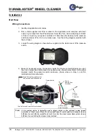
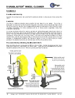
DURABLASTER
®
WHEEL CLEANER
14
Belanger, Inc.® * PO BOX 5470 * Northville, MI 48167-5470 * Ph (248) 349-7010 * Fax (248) 380-9681
1MANUL054
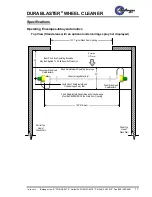
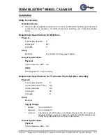
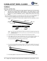
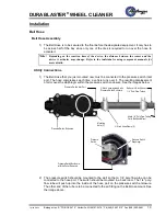
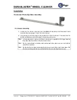
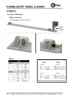
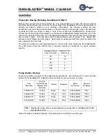
Installation
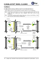
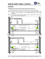
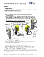
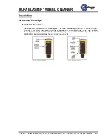
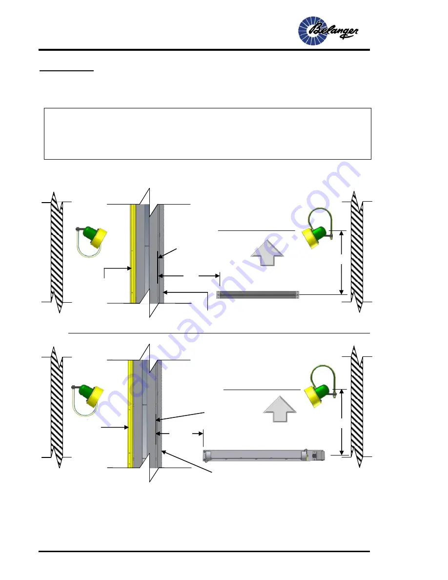
DuraBlaster® Assembly and Placement-Tunnel Activation Devices
See the diagrams below for correct placement of activation devices in a tunnel application.
Note:
The Bell Hose and the Photo-eyes are for use with system controllers that do NOT have tire
tracking. Use those sensing devices with a Belanger® Wheel Sensor Timer for each
DuraBlaster®.
Note:
See the tunnel controller manual for further information on the use of the Bell Hose or Photo-
eyes to track tires with the controller’s tracking system.
Bell Hose
Photo-Eye
Center Line
of Bell Hose
36”
TY
P
36”
TY
P
34”
26 1/2”
Center Line of DuraBlaster®
Center Line of DuraBlaster®
Center Line of
Photo Eyes
Direction
of Travel
Direction
of Travel
Inside of Conveyor
Inner Guide Rail
Partial Top
View of
Wash Wall
Conveyor Inner Guide Rail
Partial Top
View of the
Conveyor
Partial Top
View of
Wash Wall
Conveyor Outer
Guide Rail
Inside of Conveyor
Inner Guide Rail
Conveyor Inner Guide Rail
Conveyor Outer
Guide Rail
Partial Top
View of
Wash Wall
Partial Top
View of the
Conveyor
Partial Top
View of
Wash Wall


