DURABLASTER
®
WHEEL CLEANER
1MANUL054
Belanger, Inc.® * PO BOX 5470 * Northville, MI 48167-5470 * Ph (248) 349-7010 * Fax (248) 380-9681
17
Installation
Utility Connections
Activation Device:
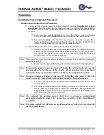
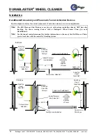
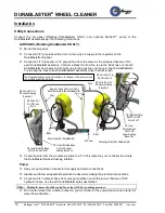
Please see the appropriate sensing device manual or DuraBlaster® Assembly and Placement
in this manual, as necessary, for further instructions regarding your rotational activation
device.
Requirement Specifications for Bell Hose
Phys
i
cal
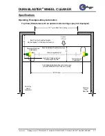
Tunnel space required
5”
Unit Length
48”
Unit width
5”
Utility
Electrical
Dry Contact (Controller Input Voltage)
Output Specifications
Physical
Vehicle clearance, width NA
Utility
Field Supplied 1/4” Poly Flow tubing
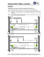
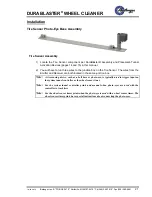
Requirement Specifications for Tire Sensor Photo-Eye Base Assembly
Physical
Tunnel space required
6”
Unit height Receiver / Timer
NA
Unit height Emitter
NA
Unit Length
68”
Unit width
6”
Utility
Electrical
Supply Voltage
*
Emitter:
10 to 30 Volts DC
*
Receiver:
10 to 30 Volts DC
*
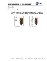
Indicator:
The internal red LED lights are activated whenever the AC receiver is
activated. Emitters have a red “power on” indicator LED. All indicators are
visible through the lens or from the side of the sensor.
Output Specifications
Physical
Vehicle clearance, width NA


