FLIPPING™ ARCH
14
Belanger, Inc.® *PO BOX 5470 *Northville, MI 48167-5470 * Ph (248) 349-7010 * Fax (248) 380-9681
1MANUL027
Installation
Arch Assembly
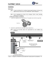
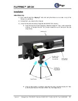
3. Stand the Arch up so that the Flipping Cylinder Assembly is facing the Exit of the tunnel. See
the image below.
Position the Arch so that the distance between the back of the Driver side Leg and the
inside edge of the conveyor guiderail is 49-3
/8”.
Square and Level the Driver Side Leg Assembly to the tunnel.
Lag the Driver Side Leg Assembly to the ground.
Square and Level the Passenger Side Leg Assembly to the Driver Side Leg Assembly
and the tunnel.
Lag the Passenger Side Leg Assembly to the ground.
Direction
Of Travel
View of the Arch facing the EXIT side of the Arch
and the ENTRANCE side of the tunnel
Leg Assembly on
Passenger Side
Head Assembly
Cylinder Assembly
49-
3/8”
Leg Assembly on
Driver Side
Back of Driver Side
Leg Assembly
Inside of Conveyor Guiderail
Conveyor
Ground Lag
(4) per Leg
Assembly
Ground Lag
(4) per Leg
Assembly
Floor Line


