INSTALLATION AND STARTUP
1MANUL220
Belanger, Inc.® * PO BOX 5470. * Northville, MI 48167-5470 * Ph (248) 349-7010 * Fax (248) 380-9681
4-27
Chapter 4 Frame and Carriage Assembly
Passenger Side Boom Install
Optional HydroBlade®/ Wheel Cleaner Manifold Accessories
To reorient the components shown below from a Driver side equipment room to a Passenger side
equipment room configuration; see the following instructions:
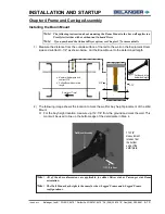
Lexair™ Distribution Manifold
1)
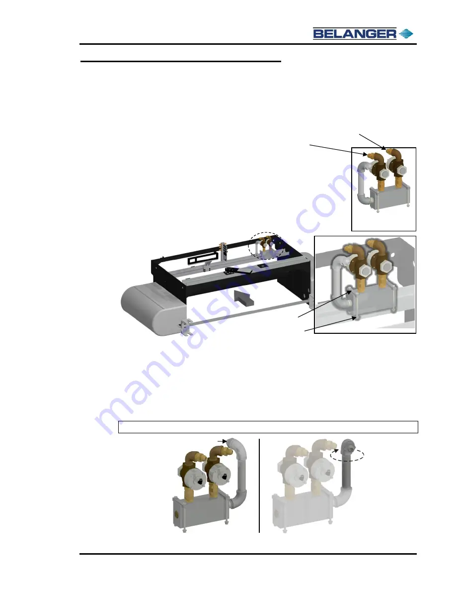
Locate the Lexair™ Manifold assembly near the top of the carriage on the passe
nger
side.
Disconnect both ends of each hydraulic hose (2) that is routed from the
Lexair™ Manifold to the Center Feed
Manifolds. See the image to the right.
2)
Remove the four 5/16-
18 fasteners, flat washers, Nylock™ nuts, and the two clamps
that are holding the manifold assembly to the carriage c-channel as shown below.
3)
Move the manifold assembly to a workbench that has a vice on it so that you can rotate the fittings around to
their appropriate orientation.
Once at the workbench, loosen the brass s
wivel fittings that hold the Lexair™
Valves in place.
Remove the Lexair™ Valves and set them off to the side.
4)
Turn the top elbow so that the Main Feed Connection faces the entrance side of the machine and is angled
toward the outside of the carriage as shown below.
Note:
Make sure that all the other fittings stay tight!
Lexa
ir™ Manifold
Before
After
Main Feed Connection
Inner Lexair™ Hose
to HydroBlade® center feed manifold
Outer Lexair™ Hose
to Wheel Cleaner center feed manifold
5/16-18 fasteners, flat washers,
Nylock
™
nuts (4) of each
Clamp (2)
Summary of Contents for FreeStyler
Page 1: ...FreeStyler Installation Startup FreeStyler Installation Startup 1MANUAL220 Rev14 ...
Page 2: ......
Page 4: ......
Page 12: ......
Page 13: ... Chapter 1 Introduction Chapter 1 Introduction ...
Page 14: ......
Page 26: ......
Page 28: ......
Page 31: ... Chapter 3 Getting Started Chapter 3 Getting Started ...
Page 32: ......
Page 52: ......
Page 53: ... Chapter 4 Frame and Carriage Assembly Chapter 4 Frame and Carriage Assembly ...
Page 54: ......
Page 123: ... Chapter 5 Entrance and Exit Photo Eyes Chapter 5 Entrance and Exit Photo Eyes ...
Page 124: ......
Page 135: ... Chapter 6 Treadle Assembly Chapter 6 Treadle Assembly ...
Page 136: ......
Page 142: ......
Page 144: ......
Page 151: ... Chapter 8 MixStir Options Chapter 8 MixStir Options Triple Foam and High Pressure Wax ...
Page 152: ......
Page 163: ... Chapter 9 Reclaim Water Adapter Kit Option Chapter 9 Reclaim Water Adapter Kit Option ...
Page 164: ......
Page 167: ... Chapter 10 Booster Pump Assembly Option Chapter 10 Booster Pump Assembly Option ...
Page 168: ......
Page 174: ......
Page 175: ... Chapter 11 Bug Spray Applicator Option Chapter 11 Bug Spray Applicator Option ...
Page 176: ......
Page 183: ... Chapter 12 Undercarriage Options Chapter 12 Undercarriage Options ...
Page 184: ......
Page 191: ... Chapter 13 Water Softener Option Chapter 13 Water Softener Option ...
Page 192: ......
Page 205: ... Chapter 14 HydroBlade Assembly Option Chapter 14 HydroBlade Assembly Option ...
Page 206: ......
Page 226: ......
Page 249: ... Chapter 16 Signage Options Chapter 16 Signage Options ...
Page 250: ......
Page 253: ... Chapter 17 Onboard Dryer Option Chapter 17 Onboard Dryer Option ...
Page 254: ......
Page 258: ......
Page 259: ... Chapter 18 Spot Free Rinse R O Option Chapter 18 Spot Free Rinse R O Option ...
Page 260: ......
Page 264: ......
Page 265: ... Chapter 19 Trades Chapter 19 Trades ...
Page 266: ......
Page 270: ......
Page 271: ... Chapter 20 Electrical Chapter 20 Electrical ...
Page 272: ......
Page 282: ......
Page 284: ......
Page 293: ... Chapter 22 Initial Startup Chapter 22 Initial Startup ...
Page 294: ......
Page 320: ......
Page 321: ......

