INSTALLATION AND STARTUP
1MANUL220
Belanger, Inc.® * PO BOX 5470. * Northville, MI 48167-5470 * Ph (248) 349-7010 * Fax (248) 380-9681
5-1
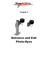
Chapter 5 Entrance and Exit Photo-Eyes
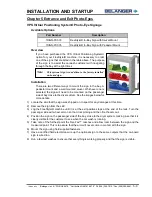
Photo Eye Placement
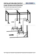
All Photo-Eye placement from entrance to exit,
including the VPS Virtual Positioning System® is
covered in this chapter and on the 11 x 17 pages at
the end of this manual.
Photo-Eye Available Style Options
Part Number
Description
PE 105854
Photo Eye Set (Floor Mounted)
PE 105855
Photo Eye Set (Wall Mounted)
Photo-Eye Available Add-on Options
Part Number
Description
PE 105858
Heating Kit (1 Set)
PE 105859
Heating Kit (2 Sets)
Note:
Read through this entire section to familiarize yourself with the Photo-Eye requirements
before installation.
Photo-Eye Layout and Description
This single set can handle up to 5 functions (3 Enter operations, Door Operation and POS
Communication). Some of the typical items that are controlled by a single set of Photo-Eyes are Rust
Inhibitor, Undercarriage Wash and machine activation.
If On-Board Door Controls are utilized, the site must have at least two sets of Photo-Eyes. One set for
the entrance and one set for the exit.
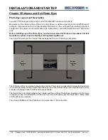
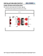
The Photo-Eyes should be installed as close as possible to the entrance and exit door tracks and off-
set by 6” as shown below.
Photo-Eyes
with 6” Off
-Set
Direction of Travel
Exit
Door
Tracks
Entrance
Door
Tracks
Photo-Eyes
with 6” Off
-Set
Image Shown with Wall Mounted Photo-Eyes
Summary of Contents for FreeStyler
Page 1: ...FreeStyler Installation Startup FreeStyler Installation Startup 1MANUAL220 Rev14 ...
Page 2: ......
Page 4: ......
Page 12: ......
Page 13: ... Chapter 1 Introduction Chapter 1 Introduction ...
Page 14: ......
Page 26: ......
Page 28: ......
Page 31: ... Chapter 3 Getting Started Chapter 3 Getting Started ...
Page 32: ......
Page 52: ......
Page 53: ... Chapter 4 Frame and Carriage Assembly Chapter 4 Frame and Carriage Assembly ...
Page 54: ......
Page 123: ... Chapter 5 Entrance and Exit Photo Eyes Chapter 5 Entrance and Exit Photo Eyes ...
Page 124: ......
Page 135: ... Chapter 6 Treadle Assembly Chapter 6 Treadle Assembly ...
Page 136: ......
Page 142: ......
Page 144: ......
Page 151: ... Chapter 8 MixStir Options Chapter 8 MixStir Options Triple Foam and High Pressure Wax ...
Page 152: ......
Page 163: ... Chapter 9 Reclaim Water Adapter Kit Option Chapter 9 Reclaim Water Adapter Kit Option ...
Page 164: ......
Page 167: ... Chapter 10 Booster Pump Assembly Option Chapter 10 Booster Pump Assembly Option ...
Page 168: ......
Page 174: ......
Page 175: ... Chapter 11 Bug Spray Applicator Option Chapter 11 Bug Spray Applicator Option ...
Page 176: ......
Page 183: ... Chapter 12 Undercarriage Options Chapter 12 Undercarriage Options ...
Page 184: ......
Page 191: ... Chapter 13 Water Softener Option Chapter 13 Water Softener Option ...
Page 192: ......
Page 205: ... Chapter 14 HydroBlade Assembly Option Chapter 14 HydroBlade Assembly Option ...
Page 206: ......
Page 226: ......
Page 249: ... Chapter 16 Signage Options Chapter 16 Signage Options ...
Page 250: ......
Page 253: ... Chapter 17 Onboard Dryer Option Chapter 17 Onboard Dryer Option ...
Page 254: ......
Page 258: ......
Page 259: ... Chapter 18 Spot Free Rinse R O Option Chapter 18 Spot Free Rinse R O Option ...
Page 260: ......
Page 264: ......
Page 265: ... Chapter 19 Trades Chapter 19 Trades ...
Page 266: ......
Page 270: ......
Page 271: ... Chapter 20 Electrical Chapter 20 Electrical ...
Page 272: ......
Page 282: ......
Page 284: ......
Page 293: ... Chapter 22 Initial Startup Chapter 22 Initial Startup ...
Page 294: ......
Page 320: ......
Page 321: ......


