INSTALLATION AND STARTUP
1MANUL220
Belanger, Inc.® * PO BOX 5470. * Northville, MI 48167-5470 * Ph (248) 349-7010 * Fax (248) 380-9681
5-5
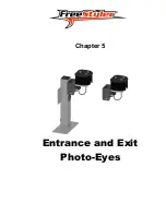
Chapter 5 Entrance and Exit Photo-Eyes
Miscellaneous
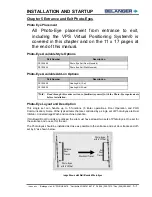
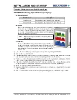
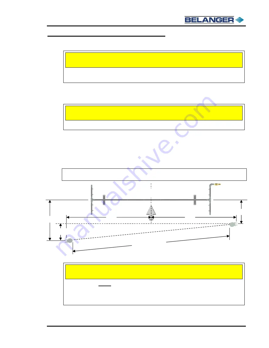
The Photo Eyes are positioned just inside of the bay, behind any door returns. Make sure the photo eyes are placed
so the Undercarriage Wash does not spray into the beams (see example below). Also see the following large format
drawings in this section for more details.
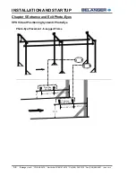
In very short bays it may be necessary to place the Photo Eyes on the outside of the building. Refer to your site-
specific plans for more detail.
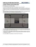
1)
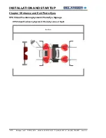
Place the tal
ler, driver side, photo eye at 21” f
rom the center of the main manifold of the undercarriage wash to the center
of the leg of the photo eye.
2)
Position the shorter, passenger side, photo eye at 15” from the center of the main manifold of the undercarriage wa
sh to
the center of the leg of the photo eye.
Note:
You should have the “receiver” Photo Eye (tall stand, if floor mounted) with its back to any
direct sun light. Direct sunlight may adversely affect the performance.
Overhead View
The above image shows the correct clearance and offset angle required for both Photo Eye styles to operate properly.
Centerline of
bay
Passenger Side
Clear of any vehicle path
6
”
12”
Direction of
Travel
21”
15”
6” offset
Driver Side
Allow space for the Undercarriage Wash and/or Rocker Blaster/Rocker Spin Cleans and
adequate vehicle clearance.
Special Considerations
Photo Eyes MUST be clear of the door, door openers and the path of the manifold’s travel.
CAUTION
The offset angle MUST be great enough, so the light beams do not make contact between the
bed and cab of a pickup truck (6” minimum).
If possible, leave access around the backside of the Photo Eyes so that you do not have to
walk in front of them and risk activating the system.
CAUTION
Summary of Contents for FreeStyler
Page 1: ...FreeStyler Installation Startup FreeStyler Installation Startup 1MANUAL220 Rev14 ...
Page 2: ......
Page 4: ......
Page 12: ......
Page 13: ... Chapter 1 Introduction Chapter 1 Introduction ...
Page 14: ......
Page 26: ......
Page 28: ......
Page 31: ... Chapter 3 Getting Started Chapter 3 Getting Started ...
Page 32: ......
Page 52: ......
Page 53: ... Chapter 4 Frame and Carriage Assembly Chapter 4 Frame and Carriage Assembly ...
Page 54: ......
Page 123: ... Chapter 5 Entrance and Exit Photo Eyes Chapter 5 Entrance and Exit Photo Eyes ...
Page 124: ......
Page 135: ... Chapter 6 Treadle Assembly Chapter 6 Treadle Assembly ...
Page 136: ......
Page 142: ......
Page 144: ......
Page 151: ... Chapter 8 MixStir Options Chapter 8 MixStir Options Triple Foam and High Pressure Wax ...
Page 152: ......
Page 163: ... Chapter 9 Reclaim Water Adapter Kit Option Chapter 9 Reclaim Water Adapter Kit Option ...
Page 164: ......
Page 167: ... Chapter 10 Booster Pump Assembly Option Chapter 10 Booster Pump Assembly Option ...
Page 168: ......
Page 174: ......
Page 175: ... Chapter 11 Bug Spray Applicator Option Chapter 11 Bug Spray Applicator Option ...
Page 176: ......
Page 183: ... Chapter 12 Undercarriage Options Chapter 12 Undercarriage Options ...
Page 184: ......
Page 191: ... Chapter 13 Water Softener Option Chapter 13 Water Softener Option ...
Page 192: ......
Page 205: ... Chapter 14 HydroBlade Assembly Option Chapter 14 HydroBlade Assembly Option ...
Page 206: ......
Page 226: ......
Page 249: ... Chapter 16 Signage Options Chapter 16 Signage Options ...
Page 250: ......
Page 253: ... Chapter 17 Onboard Dryer Option Chapter 17 Onboard Dryer Option ...
Page 254: ......
Page 258: ......
Page 259: ... Chapter 18 Spot Free Rinse R O Option Chapter 18 Spot Free Rinse R O Option ...
Page 260: ......
Page 264: ......
Page 265: ... Chapter 19 Trades Chapter 19 Trades ...
Page 266: ......
Page 270: ......
Page 271: ... Chapter 20 Electrical Chapter 20 Electrical ...
Page 272: ......
Page 282: ......
Page 284: ......
Page 293: ... Chapter 22 Initial Startup Chapter 22 Initial Startup ...
Page 294: ......
Page 320: ......
Page 321: ......


