INSTALLATION AND STARTUP
3-16
Belanger, Inc.® * PO BOX 5470. * Northville, MI 48167-5470 * Ph (248) 349-7010 * Fax (248) 380-9681
1MANUL220
Chapter 3 Getting Started
FreeStyler® Position Considerations
Note:
Using the previously stated considerations and the site overview, determine if the machine needs to be
installed off-center from the doors, and/or if either side arm will need to be de-stroked to maintain
clearance. Record the information below.
Considering the length, width and height issues previously discussed, answer the following questions.
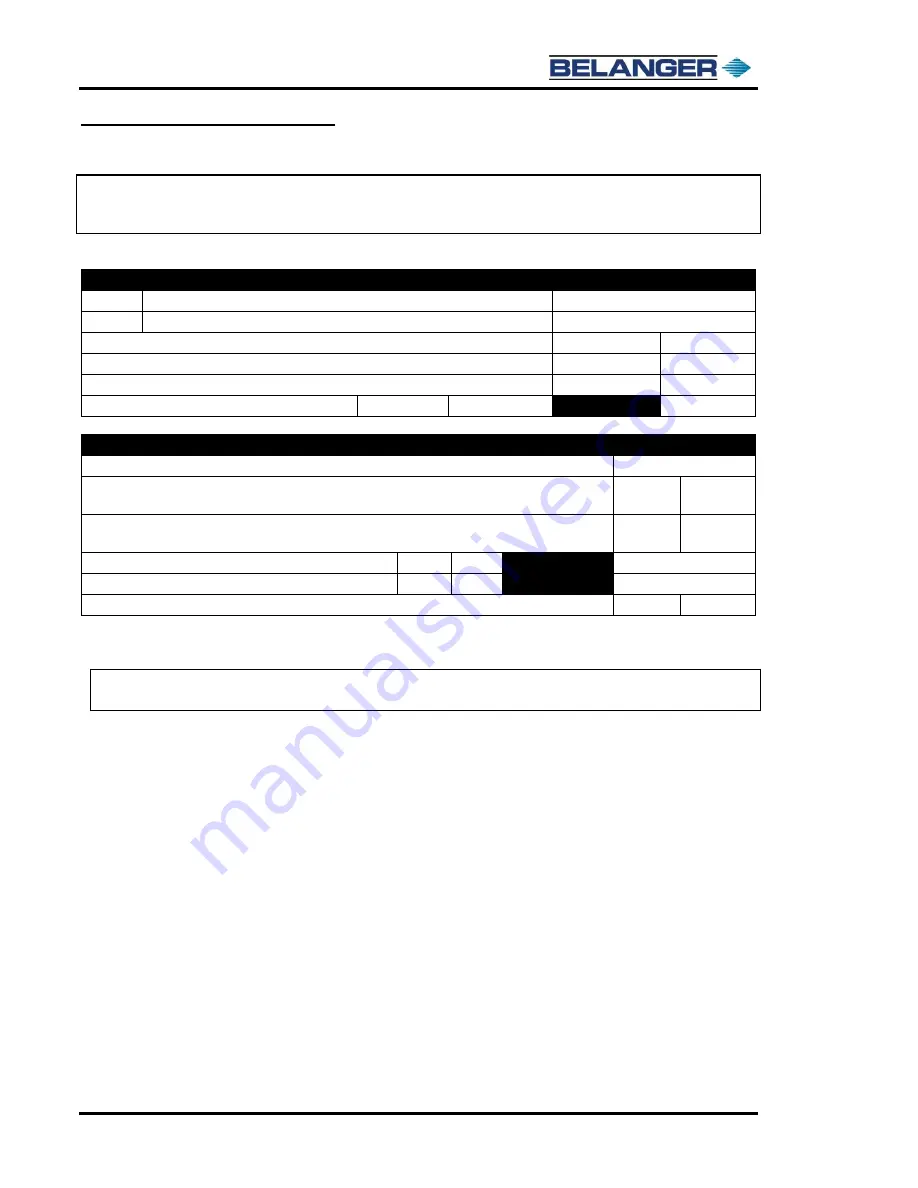
Summary of Width Considerations
Record Here
P
From centerline of door to the passenger side wall
D
From centerline of door to the driver side wall
I will need to de-stroke the passenger side arm
YES
NO
I will need to de-stroke the driver side arm
YES
NO
I would like to align the center of the rails to the center of the doors
YES
NO
If not, shift the center of the rails towards the….
Driver side
Passenger side
How Far (inches)
Summary of Length Considerations
Record Here
What is the maximum length vehicle you plan to wash?
4-Legged Frame:
Treadle and vehicle should be set to factory spec of 9” behind entrance
side of exit 4 x 6 leg
YES
NO
6-Legged Frame:
Treadle and vehicle should be set to factory spec of 49” behin
d entrance
side of exit 4 x 6 leg
YES
NO
If no, will I move the Treadle forward (toward the exit)?
YES
NO
How Far (inches)
Will I have to move the End Limit Stop?
YES
NO
How Far (inches)
Will I need “Small Bay” software?
YES
NO
Using the above width and length consideration charts and the two layout drawings, determine the exit
leg position in the bay.
Note:
The head beams are 190” long and made for buildings 16’-0” (192”) or greater. If P + D is less
than 192” in the area of the head beams, they must be cut to a length 2” shorter than P + D.
Summary of Contents for FreeStyler
Page 1: ...FreeStyler Installation Startup FreeStyler Installation Startup 1MANUAL220 Rev14 ...
Page 2: ......
Page 4: ......
Page 12: ......
Page 13: ... Chapter 1 Introduction Chapter 1 Introduction ...
Page 14: ......
Page 26: ......
Page 28: ......
Page 31: ... Chapter 3 Getting Started Chapter 3 Getting Started ...
Page 32: ......
Page 52: ......
Page 53: ... Chapter 4 Frame and Carriage Assembly Chapter 4 Frame and Carriage Assembly ...
Page 54: ......
Page 123: ... Chapter 5 Entrance and Exit Photo Eyes Chapter 5 Entrance and Exit Photo Eyes ...
Page 124: ......
Page 135: ... Chapter 6 Treadle Assembly Chapter 6 Treadle Assembly ...
Page 136: ......
Page 142: ......
Page 144: ......
Page 151: ... Chapter 8 MixStir Options Chapter 8 MixStir Options Triple Foam and High Pressure Wax ...
Page 152: ......
Page 163: ... Chapter 9 Reclaim Water Adapter Kit Option Chapter 9 Reclaim Water Adapter Kit Option ...
Page 164: ......
Page 167: ... Chapter 10 Booster Pump Assembly Option Chapter 10 Booster Pump Assembly Option ...
Page 168: ......
Page 174: ......
Page 175: ... Chapter 11 Bug Spray Applicator Option Chapter 11 Bug Spray Applicator Option ...
Page 176: ......
Page 183: ... Chapter 12 Undercarriage Options Chapter 12 Undercarriage Options ...
Page 184: ......
Page 191: ... Chapter 13 Water Softener Option Chapter 13 Water Softener Option ...
Page 192: ......
Page 205: ... Chapter 14 HydroBlade Assembly Option Chapter 14 HydroBlade Assembly Option ...
Page 206: ......
Page 226: ......
Page 249: ... Chapter 16 Signage Options Chapter 16 Signage Options ...
Page 250: ......
Page 253: ... Chapter 17 Onboard Dryer Option Chapter 17 Onboard Dryer Option ...
Page 254: ......
Page 258: ......
Page 259: ... Chapter 18 Spot Free Rinse R O Option Chapter 18 Spot Free Rinse R O Option ...
Page 260: ......
Page 264: ......
Page 265: ... Chapter 19 Trades Chapter 19 Trades ...
Page 266: ......
Page 270: ......
Page 271: ... Chapter 20 Electrical Chapter 20 Electrical ...
Page 272: ......
Page 282: ......
Page 284: ......
Page 293: ... Chapter 22 Initial Startup Chapter 22 Initial Startup ...
Page 294: ......
Page 320: ......
Page 321: ......


