INSTALLATION AND STARTUP
4-16
Belanger, Inc.® * PO BOX 5470. * Northville, MI 48167-5470 * Ph (248) 349-7010 * Fax (248) 380-9681
1MANUL220
Chapter 4 Frame and Carriage Assembly
Sonar Placement
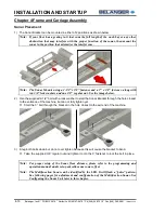
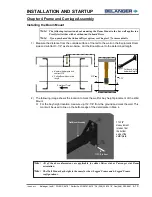
1) The Sonar Bracket can be mounted in either of 2 positions as shown below.
Note:
If your floor has a grating in it that runs the full length of the wash bay or any other
obstruction that may interfere with the proper function of the sonar, then mount the
sonar in the position that minimizes the interference.
Note:
The Sonar Mounts using a 2-1/2’’x 3/8” fastener and a 3’’ x 3/8” fastener, along with
two 3/8” lock washers and one 3/8’’ regular nut. See the image below.
2) Use the supplied 2-1
/2’’ bolt with a lock washer to start the Sonar Bracket through the hole closest
to the entrance of the machine, but do not fully tighten yet.
Start the 3’’ bolt through the bracket in the hole closest to the exit end of the machine.
3) Snug both bolts down but do not over tighten because this will cause the bracket to bend.
Take the supplied 3/8’’ regular nut and tighten it onto the 3’’ fastener to lock the bolt in place.
Note:
For proper setup of the Sonar floor distance, please refer to the programming and
operation manual under setup miscellaneous sonar offset.
Note:
The Multifunction Sonar can be identified by the LED. It will flash a “pulse” pattern.
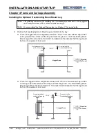
See following pages for adjustment and configuration of the Multifunction Sonar. See
Configuring the Sonar Unit later in this chapter.
Summary of Contents for FreeStyler
Page 1: ...FreeStyler Installation Startup FreeStyler Installation Startup 1MANUAL220 Rev14 ...
Page 2: ......
Page 4: ......
Page 12: ......
Page 13: ... Chapter 1 Introduction Chapter 1 Introduction ...
Page 14: ......
Page 26: ......
Page 28: ......
Page 31: ... Chapter 3 Getting Started Chapter 3 Getting Started ...
Page 32: ......
Page 52: ......
Page 53: ... Chapter 4 Frame and Carriage Assembly Chapter 4 Frame and Carriage Assembly ...
Page 54: ......
Page 123: ... Chapter 5 Entrance and Exit Photo Eyes Chapter 5 Entrance and Exit Photo Eyes ...
Page 124: ......
Page 135: ... Chapter 6 Treadle Assembly Chapter 6 Treadle Assembly ...
Page 136: ......
Page 142: ......
Page 144: ......
Page 151: ... Chapter 8 MixStir Options Chapter 8 MixStir Options Triple Foam and High Pressure Wax ...
Page 152: ......
Page 163: ... Chapter 9 Reclaim Water Adapter Kit Option Chapter 9 Reclaim Water Adapter Kit Option ...
Page 164: ......
Page 167: ... Chapter 10 Booster Pump Assembly Option Chapter 10 Booster Pump Assembly Option ...
Page 168: ......
Page 174: ......
Page 175: ... Chapter 11 Bug Spray Applicator Option Chapter 11 Bug Spray Applicator Option ...
Page 176: ......
Page 183: ... Chapter 12 Undercarriage Options Chapter 12 Undercarriage Options ...
Page 184: ......
Page 191: ... Chapter 13 Water Softener Option Chapter 13 Water Softener Option ...
Page 192: ......
Page 205: ... Chapter 14 HydroBlade Assembly Option Chapter 14 HydroBlade Assembly Option ...
Page 206: ......
Page 226: ......
Page 249: ... Chapter 16 Signage Options Chapter 16 Signage Options ...
Page 250: ......
Page 253: ... Chapter 17 Onboard Dryer Option Chapter 17 Onboard Dryer Option ...
Page 254: ......
Page 258: ......
Page 259: ... Chapter 18 Spot Free Rinse R O Option Chapter 18 Spot Free Rinse R O Option ...
Page 260: ......
Page 264: ......
Page 265: ... Chapter 19 Trades Chapter 19 Trades ...
Page 266: ......
Page 270: ......
Page 271: ... Chapter 20 Electrical Chapter 20 Electrical ...
Page 272: ......
Page 282: ......
Page 284: ......
Page 293: ... Chapter 22 Initial Startup Chapter 22 Initial Startup ...
Page 294: ......
Page 320: ......
Page 321: ......


