INSTALLATION AND STARTUP
1MANUL220
Belanger, Inc.® * PO BOX 5470. * Northville, MI 48167-5470 * Ph (248) 349-7010 * Fax (248) 380-9681
4-45
Chapter 4 Frame and Carriage Assembly
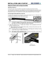
Re-engaging the Drive Shaft
1) Loosen the coupling assembly, slide the coupling away from the gearbox, towards the
center of the drive shaft.
2) Retrieve the Drive Shaft Key from the coupling and set aside.
Note:
Keep in mind that when sliding the coupling away, the key will most likely fall from the
keyway of both connecting shafts. Set it to the side until instructed to replace it.
3) Locate the Main Drive Gearbox Key and apply anti-seize to the key.
4) Line up the key slot in the gearbox with the key slot in the gearbox drive shaft.
5) Slide the Gearbox Key back into the gearbox, be sure to insert the key with the hole on the
outside of the gearbox, as shown below.
Note:
The gearbox may have to be moved or repositioned for ease of replacing (sliding in) the key.
Note:
You will know when the Gearbox Key is inserted all the way, it will bottom out in the shaft
and the hole at the end will still be visible.
6) Reinstall the Drive Shaft Key and Coupling assembly linking the two shafts back together.
Use a 9/16” wrench to tighten the coupling bolts and re-engage the drive train.
7) If the carriage has been raised using the Jack Bolt(s), raise the bolt(s) and secure it into its
raised position using the Jam Nut.
Retrieve key and set
it aside for now
Summary of Contents for FreeStyler
Page 1: ...FreeStyler Installation Startup FreeStyler Installation Startup 1MANUAL220 Rev14 ...
Page 2: ......
Page 4: ......
Page 12: ......
Page 13: ... Chapter 1 Introduction Chapter 1 Introduction ...
Page 14: ......
Page 26: ......
Page 28: ......
Page 31: ... Chapter 3 Getting Started Chapter 3 Getting Started ...
Page 32: ......
Page 52: ......
Page 53: ... Chapter 4 Frame and Carriage Assembly Chapter 4 Frame and Carriage Assembly ...
Page 54: ......
Page 123: ... Chapter 5 Entrance and Exit Photo Eyes Chapter 5 Entrance and Exit Photo Eyes ...
Page 124: ......
Page 135: ... Chapter 6 Treadle Assembly Chapter 6 Treadle Assembly ...
Page 136: ......
Page 142: ......
Page 144: ......
Page 151: ... Chapter 8 MixStir Options Chapter 8 MixStir Options Triple Foam and High Pressure Wax ...
Page 152: ......
Page 163: ... Chapter 9 Reclaim Water Adapter Kit Option Chapter 9 Reclaim Water Adapter Kit Option ...
Page 164: ......
Page 167: ... Chapter 10 Booster Pump Assembly Option Chapter 10 Booster Pump Assembly Option ...
Page 168: ......
Page 174: ......
Page 175: ... Chapter 11 Bug Spray Applicator Option Chapter 11 Bug Spray Applicator Option ...
Page 176: ......
Page 183: ... Chapter 12 Undercarriage Options Chapter 12 Undercarriage Options ...
Page 184: ......
Page 191: ... Chapter 13 Water Softener Option Chapter 13 Water Softener Option ...
Page 192: ......
Page 205: ... Chapter 14 HydroBlade Assembly Option Chapter 14 HydroBlade Assembly Option ...
Page 206: ......
Page 226: ......
Page 249: ... Chapter 16 Signage Options Chapter 16 Signage Options ...
Page 250: ......
Page 253: ... Chapter 17 Onboard Dryer Option Chapter 17 Onboard Dryer Option ...
Page 254: ......
Page 258: ......
Page 259: ... Chapter 18 Spot Free Rinse R O Option Chapter 18 Spot Free Rinse R O Option ...
Page 260: ......
Page 264: ......
Page 265: ... Chapter 19 Trades Chapter 19 Trades ...
Page 266: ......
Page 270: ......
Page 271: ... Chapter 20 Electrical Chapter 20 Electrical ...
Page 272: ......
Page 282: ......
Page 284: ......
Page 293: ... Chapter 22 Initial Startup Chapter 22 Initial Startup ...
Page 294: ......
Page 320: ......
Page 321: ......


