BELARUS-1221.2/1221
В
.2/1221.3 Description and operation
82
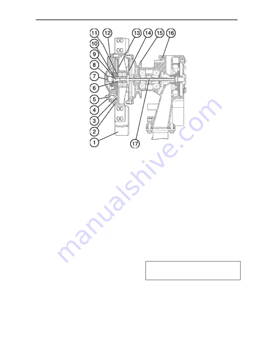
Fig. E-9.
Pump assembled with the clutch:
1 – fan blade; 2 – driven cover; 3 – hole for stop; 4 – stop nut; 5 – stop; 6 – stem; 7 – return spring; 8 –
spring holder; 9 – pusher; 10 – valve; 11 – driving disk; 12 – clutch; 13 – driven disk; 14 – drive shaft; 15 –
water pump pulley; 16 – water pump; 17 – rod.
Electrical Equipment and the Starting
System
One of electric assembly units to be in-
stalled on the engine is an 1150 W 14 V
alternator represented by a contactless
five-phase homopolar generator with one-
end magnet excitation, built-in rectifier
unit and integral voltage regulator. The
alternator is driven from the crankshaft
pulley, with a V-belt.
The engine is started by a 5.5 kW 24 V
electric starter. The starter is switch on
remotely, by means of an electromagnetic
relay and starter switch.
To facilitate the engine starting at low
temperature, the remotely-controlled glow
plugs are used installed in the cylinder
heads. The plugs, when switched on,
heat the air sucked into the cylinders.
Compressor of the pneumatic system
To ensure the reliable operation of the
tractor pneumatic system, the engine is
equipped with a single-piston, single-
stage compressor. The compressor is
mounted on the fuel distribution unit cover
flange and driven from the fuel-pump
drive gear.
Note:
With the compressor running, the
forced mode
of fan operation shall be
chosen.
Summary of Contents for 1221.2
Page 1: ...BELARUS 1221 2 1221В 2 1221 3 1221 0000010РЭ OPERATORS MANUAL 2009 ...
Page 290: ...BELARUS 1221 2 1221В 2 1221 3 Supplement 293 Electrical scheme of tractor connections ...
Page 291: ...BELARUS 1221 2 1221В 2 1221 3 Supplement 294 Variants of tractor connections ...
Page 293: ...BELARUS 1221 2 1221В 2 1221 3 Supplement 290 826 3805010 instrument board scheme ...


