1523.5-0000010 OM
103
4.3.3.3 Upper link
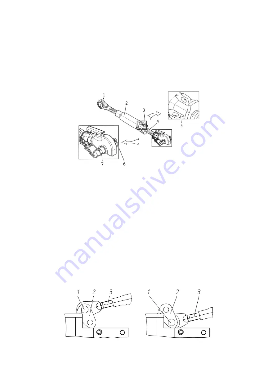
Upper link is shown in Figure 4.3.6.
The upper link length may be adjusted within 675 to 900mm.
Adjustment of the upper link length shall be made in the following order:
- unscrew counter nut 3 (figure 4.3.6);
- while rotating pipe 2 clockwise or counterclockwise with a crowbar catching ears 5,
change the upper link length;
- after adjusting the link length, locknut the screw connection with counter nut 3.
Use pin 7 of rear hinge pivot to connect upper link to the implement; mount linch pin with
ring 6 on it to fix the pin.
1 – front screw with hinge pivot assembly; 2 – pipe; 3 – counter nut; 4 – screw with a grip-
per (hinge joint); 5 – ear; 6 – linch pin; 7 – pin.
Figure 4.3.6
– Upper link
4.3.3.4 The rules of RLL adjustment for tractor operation with implements of catego-
ry 2 (LL-2)
To provide implements of category 2 coupling to the tractor RLL, it is required to do RLL
adjustment in the following way:
- if lower and upper links are completed with grippers, mount the corresponding hinge
joints of category 2 (included into SPTA) into the grippers;
- if lower and upper links are completed with hinge joints, mount the corresponding reduc-
ing bushings (included into SPTA) into the hinge joints;
- set the distance between the hinge joints (the lower links grippers) according to the dia-
gram in figure 4.3.2 by changing the buckle length. Changing the buckle length shall be
carried out by rotating guiding pin 2 (figure 4.3.4);
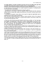
- shift the front end of upper link 3 (figure 4.3.7) from the upper hole of bracket 2 to the
lower hole;
- after the implement coupling to the lower links, couple the upper link to the implement,
adjust the upper link length if necessary.
For LL-3
For LL-2
1 – pin; 2 – bracket; 3 – upper link front end
Figure 4.3.7
– Setting of the upper link front end for operation with implements and ma-
chines of different categories


![Whirlpool [12:36:03] ?????????????????: GC900QPPB Use & Care Manual preview](http://thumbs.mh-extra.com/thumbs/whirlpool/12-36-03-gc900qppb/12-36-03-gc900qppb_use-and-care-manual_437149-01.webp)


