1523.5-0000010 OM
198
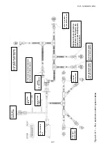
Figure 6.12.2 – Electrical circui
t diagram of RLL control system
Electronic unit
Main control
p
anel
Left re
mo
te
pa
ne
l
Righ
t rem
o
te
panel
Voltag
e valu
es f
o
r sens
o
rs sp
ec
ified i
n
th
e dia
g
ram shall
be
me
asured
wit
h
res
p
ect
to t
h
e
nega
tive sid
e of
the ele
ctro
n
ic u
n
it (
termi
nal 15
on t
h
e 25
-pi
n
co
nnec
tor),
ot
her
volta
g
e val
ues
shall be
mea
sur
ed wi
th re
-
sp
ect to
p
o
w
er su
pp
ly
ne
g
ativ
e
side
(termi
n
al 1
)
Off – 0 V
On – 10 V
Off – 0 V
On – 10 V
min
min
min
min
max
max
max
max
+ 10V
u
p
lift
lo
weri
ng
power +
power +
signal
signal
load
-
load -
load -
power +
power +
signal
load
-
0 V
0 V
0 V
10 V
10 V
0…10 V
0…10 V
0…10 V
0…10 V
Off – 0 V
On – 10 V
0 – 2 V
1 – 3 V
2 - 5 V
3 – 7 V
20 mA
20 mA
1,2…3,2 A
1,2…3,2 A
1,2…3,2 A
2,2… 7,2 V
12… 15 V
12… 15 V
5 V not charged
5 V not charged
Posit
ion
senso
r
Force
senso
r
Л
Force
senso
r
П
O –
or
ange
P – p
ink
C
– g
rey
Ф
–
vio
let
Ч
- b
lack
Elect
romagn
e
ti
c
hydraulic
governor
Ca
ble
c
o
lor
s
:
Г
– blu
e
Ж
– yel
low
З
– gr
een
K –
re
d
Кч
-
b
ro
wn
Panel lighting
Display of
Uplift
Lowering
Cut-out switch of
“damping” mode
“Damping” mode
display
Diagnostics
display
Mixing of modes
Speed of lowering
Penetration value
Uplift limitation
uplift - lowering
0 – quick lowering
1 – lowering
2 – switch off
3 - uplift


