1523.5-0000010 OM
58
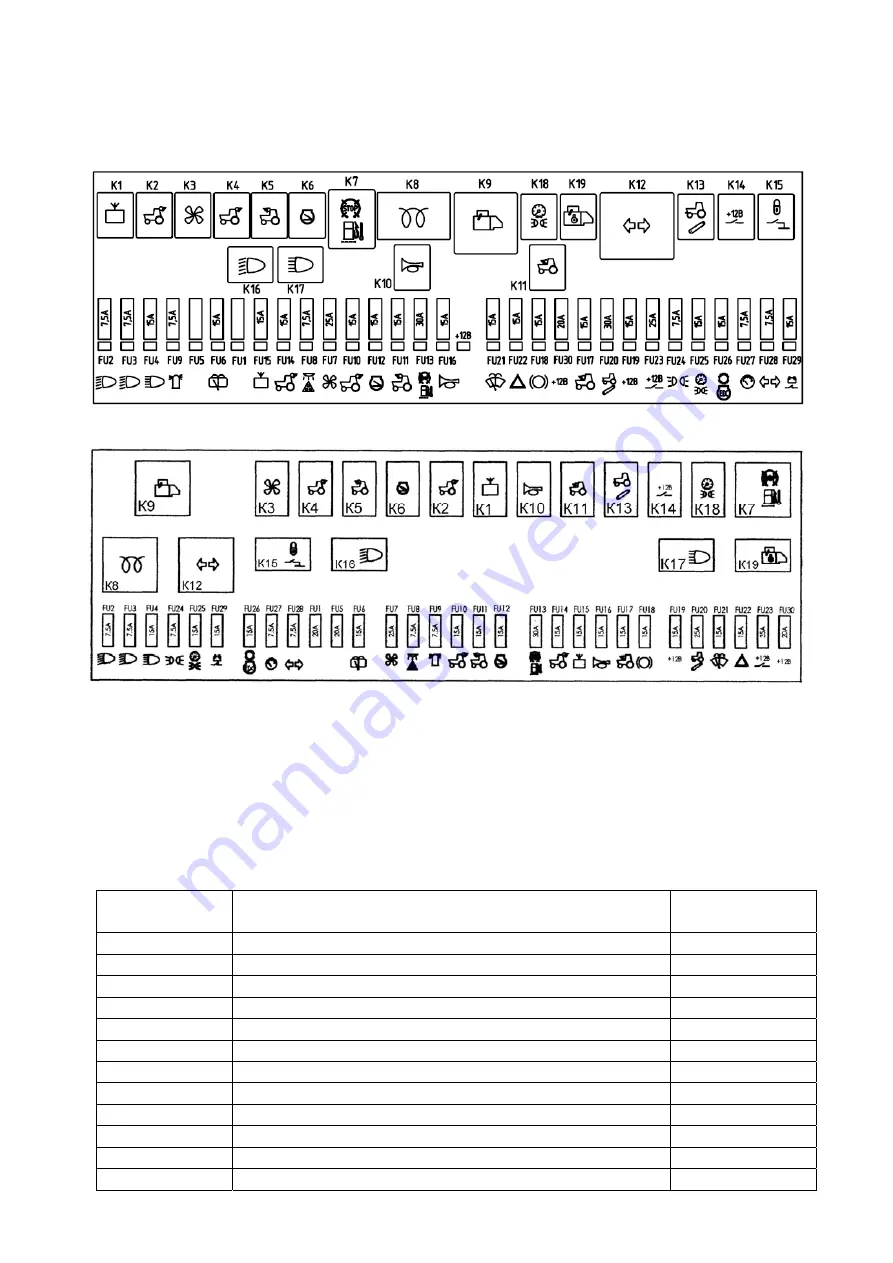
Diagram of fuses and relay location in the switching unit is shown in figure 2.20.3.
а
) Diagram of fuses and relay location in BK
А
-7.3722
b) Diagram of fuses and relay location in BK-1
Figure 2.20.3 – Diagram of fuses and relay location in the switching unit
Tables of fuses and relay assignment shown in figure 2.20.3 are stuck from inside to the
upper plastic cap 2 (figure 2.20.1) from the windscreen side.
The information on fuses and relay assignment as well as fuse ratings is given in tables
2.8 and 2.9.
Table 2.8 – Assignment of switching unit fuses
Fuse designa-
tion
Fuse assignment
(protected electric circuit)
Fuse rating
FU1 Reserve
20
А
FU2
Lower beam of right road headlight
7,5
А
FU3
Lower beam of left road headlight
7,5
А
FU4
Road headlights upper beam
15
А
FU5 Reserve
20
А
FU6
Rear screen washer and wiper
15
А
FU7
Power supply to conditioner electric motor
25
А
FU8
“Road-train” lights and cab light
7,5
А
FU9 Signal
beacon
7,5
А
FU10
Rear working lights (a pair of outer lights)
15
А
FU11
Front working lights (on the roof)
15
А
FU12 Not
used
15
А

