1523.6-0000010 OM
50
2.17 Control of rear lift linkage (RLL) with the hydraulic lift
2.17.1 General information on rules of RLL control
RLL is controlled with control panel (figure 2.17.1) and remote buttons 4 and 5 (figure
2.17.3). If there are any failures in the RLL electronic-hydraulic control system, a diagnos-
tics annunciator 5 (figure 2.17.1) displays information on the failure and, if necessary, the
operation of RLL control system is blocked.
2.17.2 RLL control panel
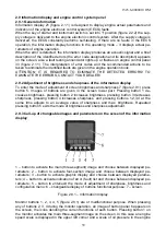
RLL control panel, located on a side console in tractor cab, is shown in figure 2.17.1.
1 – retainer of RLL control handle blocking; 2 – button of “dampening” mode activa-
tion; 3 – annunciator of “dampening” mode activation (orange color); 4 – handle to adjust
depth of soil tillage; 5 – troubleshooting annunciator (red color); 6 – handle to adjust height
limit of linkage uplifting; 7 – handle to adjust speed of lowering; 8 – handle to select control
method; 9 – annunciator of linkage lowering (green color); 10 – annunciator of linkage up-
lifting (red color); 11 – handle of RLL control.
Figure 2.17.1
– RLL control panel
The order of RLL control is the following:
- set a method of control depending on type of operation with handle 8 (figure 2.17.1).
Turning the handle clockwise against the stop is a position method of control; contraclock-
wise against the stop – draft control; in between – combined control; the combined control
is preferential;
- set the required admissible height of implement uplifting in transport condition with han-
dle 6. Turning the handle clockwise against the stop corresponds to max. uplifting, contra-
clockwise against the stop - to min. uplifting;
- set the tillage depth with handle 4. Turning the handle clockwise against the stop corre-
sponds to min. depth, contraclockwise up to “A” position corresponds to max depth; turn-
ing the handle contraclockwise against the stop corresponds to floating position;
- lower the linkage by moving handle 7 to a lower fixed position.
Then, during the operation it is required to adjust an implement for optimal operation con-
ditions:
- with handle 8 – combination of control methods;
- with handle 4 – depth of soil tillage.
- with handle 7 – speed of RLL lowering. Turning of the handle clockwise against the stop
corresponds to the max. speed of lowering, turning the handle contraclockwise corre-
sponds to min. speed lowering.


