2122.6-0000010 OM
132
4.3.5 The rules of agricultural implements coupling to FLL
Agricultural implements coupling to FLL is similar to RLL coupling.
First it is necessary to place hinged joints of LL lower links grippers on a lower axle
of the agricultural machine. It is required to approach the agricultural machine slowly, at
the speed of not more than 3 km/h, with the lower links grippers as low as possible, until
the grippers jaw is located under the hinge joints on the machine axle. To carry out cou-
pling, it is required to uplift front ends of the links until the hinge joints get fixed in the lower
links grippers. Mount cotter 9 (figure 4.3.9).
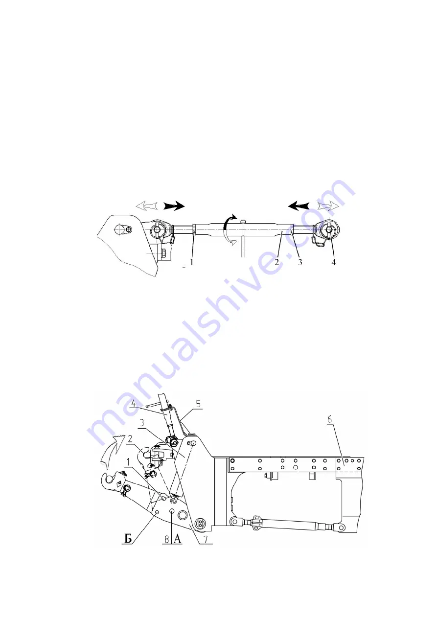
Connect upper link 5 to the agricultural machine with the help of pin 4 (figure
4.3.11), screwing in or out screwed parts with hinge joints out of tube 2 at the same time,
having unscrewed counter nuts 1, 3 before that. Further adjustment of the implement op-
erating position shall be carried out when the implement is already coupled, by changing
the length of upper link 5 (figure 4.3.9), rotating tube 2 (figure 4.3.11) with the handle. After
adjustment it is required to screw in counter nuts 1, 3.
1, 3 – counter nut; 2 – tube; 4 – pin.
Figure 4.3.11 – FLL upper link
4.3.6 The rules of shifting FLL from operating to transport position
FLL is shifted from operating to transport position in the following order:
- uplift upper link 4 (figure 4.3.12) and secure it in bracket 5;
- remove pins 8 from lower links unit 7 out of opening “A”;
- turn links 2 with grippers around pin 1 until opening “A” in turning ends of the links
matches with opening “B” in the links unit;
- insert pin 8 into the matched openings “B”.
1 – pin; 2 – lower link; 3, 5 – bracket; 4 – upper link; 6 – plate; 7 – lower links unit;
8 – pin.
Figure 4.3.12 – Transport position
https://tractormanualz.com/


