2122.6-0000010 OM
141
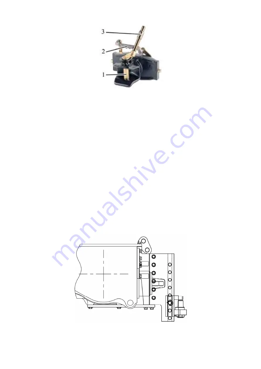
1 – center pin; 2 – handle; 3 – handle-detent for center pin;
Figure 4.4.8 – Coupling clevis KU5410/329-33
To change the attaching points in the coupling clevis lifting device along the height, it is
required to turn handle 2 (figure 4.4.8), after which the coupling clevis shall come down and get
fixed in the next lower fasteners of the lifting device. To set the coupling clevis up along the
height, it is required to turn handle 2, after which pull handle 2 up. The coupling clevis shall get
fixed in the next upper openings of the lifting device.
To couple agricultural machines to the coupling clevis, it is required to pull handle-detent 3
when center pin 1 gets unfastened, take the center pin out of the yoke opening. After that move
the tractor closer to the agricultural machine, match the agricultural machine towing eye with the
yoke jaw so that the eye opening matches with the yoke opening. Insert center pin 1 into the yoke
opening, fix it with the help of handle-detent 3.
On agreement with MTW, the customer is allowed to purchase the coupling clevis
manufactured by another company rather than “Walterscheid” and mount it onto the tractor, if
the parameters and coupling dimensions of this coupling clevis comply with the parameters
and coupling dimensions set forth in Table 4.4.7.
ATTENTION: WHEN COUPLING TRAILERS, TRAILED MACHINES, SEMI-TRAILERS
AND SEMI-TRAILED MACHINES TO THE COUPLING CLEVIS AS A PART OF DRAWBAR
HITCH, IT IS REQUIRED TO TAKE INTO ACCOUNT THAT PERMISSIBLE LOAD IN THE
HITCH POINT IN THE LONGITUDINAL DIRECTION SHALL CONSTITUTE NOT MORE
THAN 70.1 kN (INDICATED ON THE LIFTING DEVICE SIDE MEMBERS), REGARDLESS
OF THE VALUE INDICATED ON THE AUTOMATED DEVICE PLATE!
4.4.8 Piton-Fix coupling PB5329NNB33
Figure 4.4.9 – Diagram of mounting variants for Piton-Fix coupling PB5329NNB33
https://tractormanualz.com/


