2122.6-0000010 OM
186
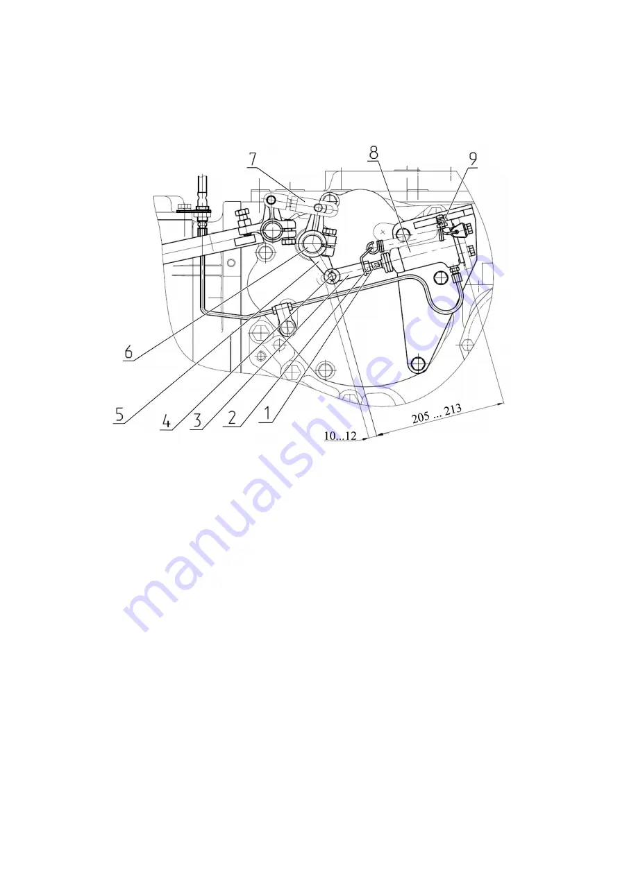
In case it is impossible to set the required dimensions by means of adjustment, it is re-
quired to remove lever 5 from brake shaft 6 after loosening tightening of the bolt for lever 5
hub, and mount it back by turning for one spline in the required direction (turn for one spline
changes dimensions for 8 mm).
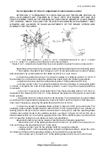
Check the length of the operating brake cylinder of the right brake in a similar way. If
necessary, mount the required length for the operating brake cylinder of the right brake ana-
logically.
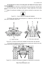
1 – shaft; 2 – counter nut; 3 – yoke; 4 – pin; 5 – lever; 6 – brake shaft; 7 – rod; 8 – op-
erating brake cylinder; 9 – overflow valve.
Figure 5.4.28 – Setting the length for the operating brake cylinder
4. Brake cylinders produced by the company “CARLISLE” (Great Britain) or produced
by the company “FENOX” (Belarus) can be mounted in service brakes control system.
On tractors with “CARLISLE” main brake cylinders after making adjustments, fill the
drive hydraulic system with brake fluid and bleed the hydraulic system in the following order:
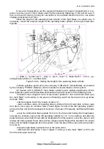
- fill tanks 3 and 4 (figure 5.4.29) of main brake cylinders 1 and 2 with brake fluid up to
the mark “MAX” on the tanks. In the process of bleeding, watch the fluid level not to go below
the mark “MIN”;
- interlock pedals 5 and 6 by means of plank “A”;
- clean overflow valves of operating brake cylinders from dirt and dust, remove caps
from them, put a pipe on overflow valve 9 head (figure 5.4.28) of the left operating cylinder,
and put its free end into the transparent container of at least 0.5l capacity, half filled with brake
fluid;
- press the interlocked brake pedals for four to five times and holding them depressed,
unscrew the overflow valve of the left operating cylinder by 1/2…3/4 revolutions and after the
pedal full travel, when half of fluid with air disappears from the system, screw the valve in and
release the brake pedals. Press them quickly, release slowly! Repeat this operation for several
times until air totally disappears from the system. Take the pipe off the valve and put a protec-
tion cap on.
- bleed the right brake hydraulic drive in the same order;
- refill fluid into both tanks 3 and 4 (figure 5.4.29) up to the mark “MAX” ((15
±
5) mm
from the tank upper butt end).
https://tractormanualz.com/


