2122.6-0000010 OM
77
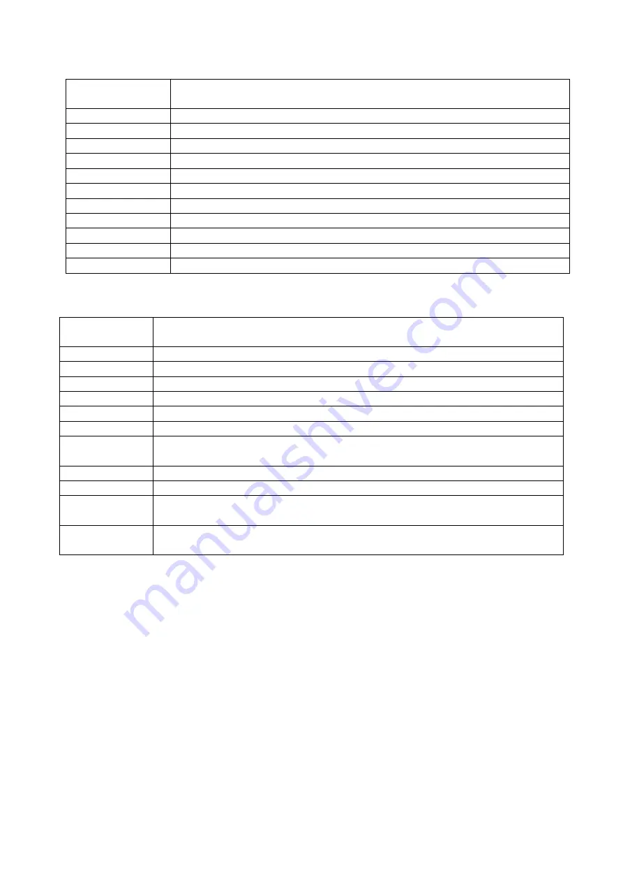
Table 2.20.4 – Relay assignment in SSU
Relay
designation
Relay assignment
К
1
Lever neutral
К
2
CECS power supply
К
3
Power supply of ECP, information monitor, diagnostic equipment
К
4 Not
used
К
5
Power supply of FLL, RLL and OPU for HLL control systems
К
6
Electrical socket after engine start 4 (figure 2.25.2)
К
7
Power supply of heaters and sensors NOx for SCR system
К
8 (Not
used)
К
9 (Not
used)
К
10 (Not
used)
К
11 (Not
used)
Table 2.20.5 – Connection of harnesses to SSU
Connector
(outlet)
Add-on element
Х
1
CECS harness
Х
2
Harness of engine electronic control system
Х
3
Harness of engine electronic control system
Х
4
Harness of FLL electronic control system
Х
5
Harness of RLL electronic control system
Х
6
Harness of OPU for HLL
Х
8
Harness of electrical sockets 3 and 4 (figure 2.25.2) and cigarette
lighter 2
Х
9
Harness of SCR system
ХТ
1
Wire of black color or with marking “
Ч
”, with lug
М
8 – “ground” of SSU
ХТ
2
Wire of yellow color or with marking “
Ж
”, with lug
М
5 – constant power
supply of SSU (+12V), regardless of AB switch position
ХТ
3
Wire of red color or with marking “
К
”, with lug
М
6 – power supply of
SSU (+12V), coming to SSU only with AB switch engaged position
https://tractormanualz.com/


