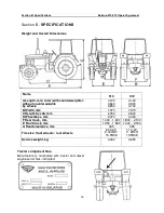
Section B. Specifications
Belarus-510/512 Operating manual
25
sensor (4).
1.2 GB operation
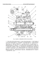
The 9F/2R GB design provides 4 forward gears and one reverse gear, each of them
can be engaged on the both range reducer stages, and one direct forward gear, at en-
gagement of which the input (31) (Fig. 1) and output (6) shaft are rigidly linked by the drive
pinion of 3rd and 6th gears (5) acting as a gear-type coupling at that.
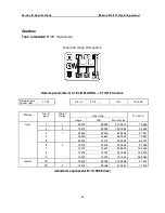
The GB gears and ranges are engaged by a single GB control lever (7) as per the
diagram (Fig. 3). Selection of gears in the GB is preceded by selection of the desired
range of the reducer.
Gears and ranges are switched only when the tractor stopped and the clutch pedal
is pressed on.
To select and engage a reducer range, the operator shifts the gear shift lever (7)
(Fig. 1) from the neutral position to the range-reducer position (Fig. 3). Further, to engage
the Ist reducer stage, the operator shifts the GB control lever (7) (Fig. 1) backwards (Fig.
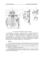
3). At that, the gear shifter lever (7) (Fig. 1), acting on the reducer rail (13) (Fig. 2), moves
it and its associated roller (9) (Fig. 1) with the fork (8) forward. The drive pinion of Ist re-
ducer stage (22) controlled by the fork (8) moves along he intermediate shaft splines (29)
and engages with the driven pinion (6) of Ist range reducer stage.
To engage the IInd reducer stage, the operator shifts the GB control lever (7) (Fig.
1) in the range reducer position forward (Fig. 3). At that, the gear shifter lever (7) (Fig. 1),
acting on the reducer rail (13) (Fig. 2), moves it and its associated roller (9) (Fig. 1) with
the fork (8) forward. The driven pinion of Ist reducer stage (22) controlled by the fork (8)
moves along he intermediate shaft splines (29) and engages with the inner gear ring of the
drive pinion (21) of IInd range reducer stage, linking it to the intermediate shaft (29). The
pinion (21) is in constant mesh with the driven pinion of the IInd range reducer stage (16).
At the IInd range reducer stage, rotation from the intermediate shaft (29) is transmit-
ted to the output shaft (6) with deceleration less than at the Ist stage.
In the GB range reducer, there is no neutral position of the drive pinion of the Ist re-
ducer stage (22) (Fig. 1), therefore either the Ist or the IInd stage is always turned on in the
range reducer.
To engage the 1st or 2nd forward or reverse gear, the operator shifts the GB control
lever (7) (Fig. 1) to the extreme left position (Fig. 3) being the position of hill-climbing gears
and reverse gears. Further, to engage the 1st or 2nd forward gear, the operator shifts the
GB control lever (7) (Fig. 1) forward (Fig. 3). At that, the gear shifter lever (7) (Fig. 1), act-
ing on the rail of the fork of the 1st gear and reverse gear, moves the fork (19) (Fig. 2)
backward. The sliding pinion of 1st gear and reverse motion (23) controlled by the fork (19)
engages with the driven pinion of 4th and 7th gears (25) (Fig. 1), and power in the GB is
transmitted to the ?GB intermediate shaft (29) through the pinions (5), (23), (22) (Fig. 2),
(23) and (25) (Fig. 1).
To engage the 1st or 2nd reverse gear, the operator shifts the GB control lever (7)
(Fig. 1) to the position of hill-climbing gears and reverse gears backward (Fig. 3). At that,
the gear shifter lever (7) (Fig. 1), acting on the rail of the fork of the 1st gear and reverse
gear, moves the fork (19) (Fig. 2) forward. The sliding pinion of 1st gear and reverse mo-
tion (23) controlled by the fork (19) engages with the intermediate pinion of reverse gear
(26) being in constant mesh with the lesser gear ring of the double-wheel pinion of 5th and
8th gears (26) (Fig. 1). At the reverse gear, power flow in the GB is transferred to the in-
termediate shaft (29) through the pinions (5), (23), (22) (Fig. 2), (23), (26) and (26) (Fig. 1).
To engage the 3rd and 6th, or 9th (direct) gear, the operator shifts the GB control

