8
9
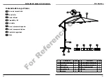
Assembly Instructions
C
D
E
F
G
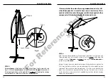
STEP 1:
Place the Top Crossbar (F) over the Bottom Crossbar (G) to form an ‘X’.
Attach the Bottom Pole (C) to the crossbars using the four M8x20 Bolts
(D) with Washers (E).
STEP 2:
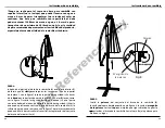
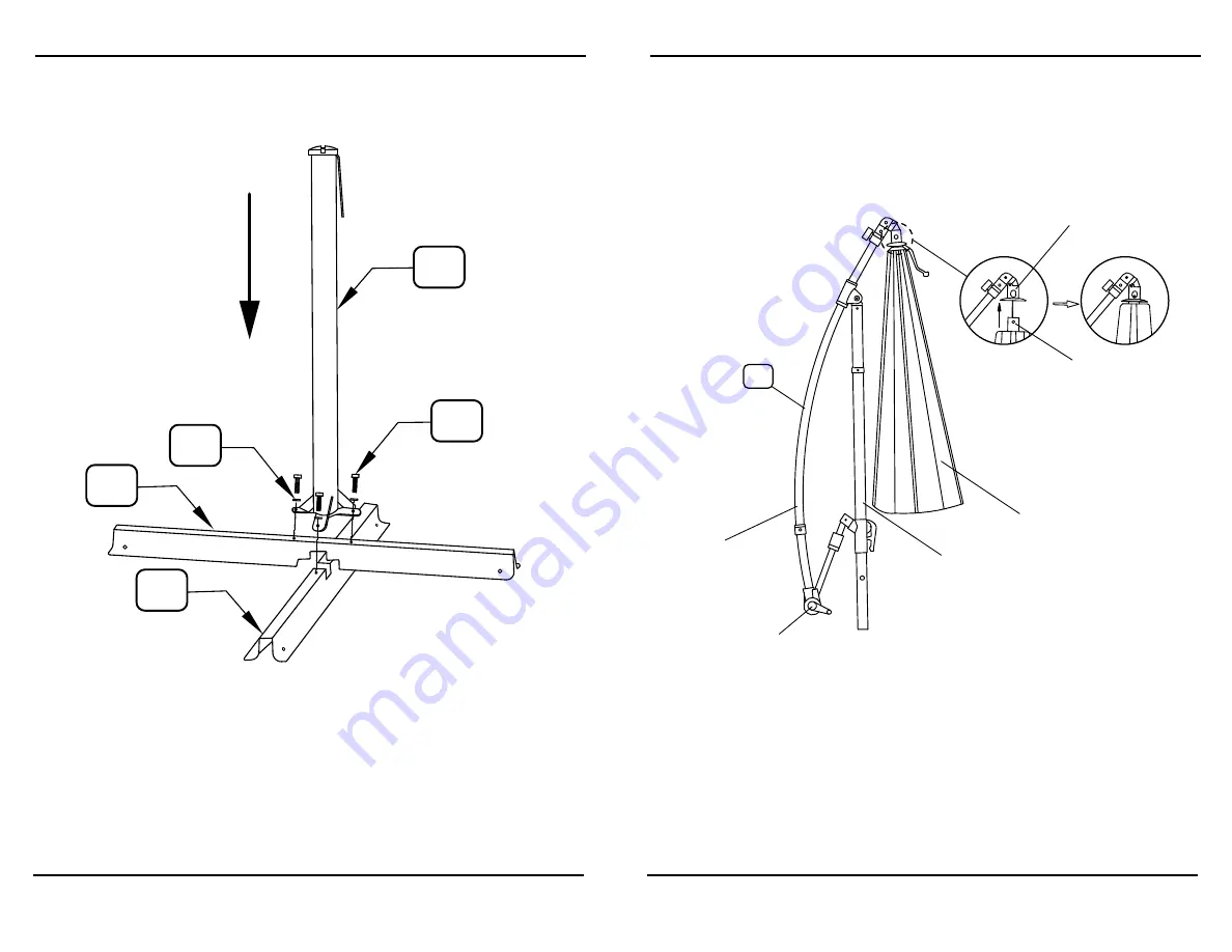
Place the Umbrella Frame (A) in the correct orientation as illustrated above,
with the
pole placed in between the umbrella canopy, and the canopy
arm. Turn the crank handle clockwise until the line inside the canopy
arm tightens some. Use the
push pins to connect the top of the umbrella
canopy to the
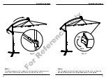
umbrella housing, see Fig. 1 & 2.
Please familiarize yourself with the descriptions for each component
of the Umbrella Frame (A) below.
Assembly Instructions
A
Fig.1
Fig.2
Fig. 11
Umbrella
Canopy
Push Pin
Umbrella Housing
Pole
Canopy
Arm
Crank
For
Reference
Only


