PX106545-EN, Rev.A
20
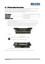
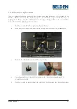
5.2.2
Electrodes replacement
The electrodes should be replaced after being used approximately 3,000 times. If the
number of arcs exceeds the replacing cycle, an electrode replacement message is
displayed on the screen. If electrodes are not replaced, splice loss increases and the
tensile force at the splicing point weakens.
i.
Turn the power off when replacing the electrodes.
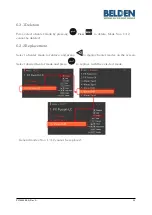
ii.
Open the wind cover and unscrew the clamp screw on the electrodes block.
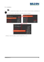
iii.
Remove the electrode block and the electrodes.
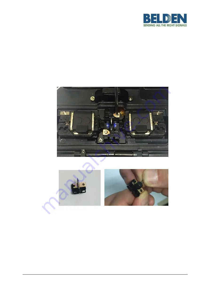
iv.
Clean the electrodes carefully by using a soft cotton swab moistened with
alcohol; then install.
v.
Turn the power on and conduct the electrode stabilization process in the menu.


