background image

PX106545-EN, Rev.A 

60 


Splicing Problem Solving


8.1


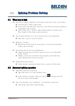
When loss is high 


Any dust or foreign substance on the fiber surface may cause a poor splice. 


Clean the fiber surface sufficiently. 


Do not clean the fiber after cleaving to prevent dust from being gathered 
in the fiber cross section. 


Lower fibers into V-grooves rather than pushing in from the sides. 
Fiber holders will facilitate proper insertion. 


Any foreign substance on V-groove hinders the correct alignment. 


Keep the V-groove clean at all times. 


Electrode condition. 


When an electrode contains an abrasion or its tip is bent and dirty, 
replace the electrodes. 


Arc amount and arc time are inappropriate. 


Check the setting of arc amount and arc time to reset them with 
proper values. 


Changes in arc time and amount are generally considered to be 
minor adjustments to factory settings. 


Inappropriate splice mode. 


Check whether appropriate splice mode is selected for the fiber 


8.2


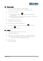
Abnormal splicing operation 


Alignment operation is repeated. 


Open the wind cover again and then close. 


If discontinues, open the wind cover, press 


and then turn off 

the power and contact Belden. 


The error message 

“Too Long Fiber” is continuously

 generated. 


Turn off the power and contact Belden. 

Summary of Contents for FX Fusion Splicer

Page 1: ...Optical Fiber Arc Fusion Splicer Read this user manual carefully before running FX Fusion Splicer FX Fusion Splicer PX106545 EN Rev A USER MANUAL...

Page 2: ...2 this device must accept any interference received including interference that may cause undesired operation Device Type Notification A Class Device Broadcasting and communication device commercial...

Page 3: ...pply 12 4 2 How to turn the power on off 14 4 3 FX Fusion Splicer Sleeve Heater 15 4 4 Splice procedure 16 4 5 Removing the spliced fiber 17 4 6 Heating protection sleeve 17 MAINTENANCE OF SPLICE QUAL...

Page 4: ...rror 59 7 7 Fiber thick error 59 7 8 Bubble error 59 7 9 Cleaved surface error 59 SPLICING PROBLEM SOLVING 60 8 1 When loss is high 60 8 2 Abnormal splicing operation 60 PROBLEM OCCURRENCES AND QUESTI...

Page 5: ...smell noise or abnormal overheating A foreign substance or liquid falls into the equipment The splicer is visibly damaged Use only the power cord and connecting devices provided with or intended for...

Page 6: ...et hands It may cause electrical shock Do not disassemble the AC charger battery or FX Fusion Splicer Deformation may cause fire electrical shock or injury Refer to the following when using the batter...

Page 7: ...age on the belt it may incur equipment damage or injury Always follow safety best practices including the use of safety goggles and protective clothing when working with fiber optic products including...

Page 8: ...electrodes Always use Belden approvedreplacements Ensure correct positioning Always replace in pairs Failure to follow all warnings and cautions to ensure proper function of the FX Fusion Splicer may...

Page 9: ...Typically 13 sec with IS 60 mode IS 60 sleeve Applicable protection sleeve 60 mm 40 mm and micro sleeves Storage of splice result Up to 5 000 data sets and 5 000 images Tension test 1 96N to 2 25N Op...

Page 10: ...r holders left and right installed 1 pair Tackle box 1 CD ROM with user manual English French and Spanish 1 USB cable 1 Carrying case 1 Carrying case keys 2 2 2 2 Optional package Belden Product Numbe...

Page 11: ...s focus VFL should load shortcut Move the cursor upward Move each motor to manual mode Splice popup menu should load Move the cursor downward Move each motor to manual mode Heater popup menu should lo...

Page 12: ...PX106545 EN Rev A 10 3 2 Component name Sleeve heater Wind cover Monitor Battery...

Page 13: ...PX106545 EN Rev A 11 Heater Heater cover Instructions for Use DC in charge in USB...

Page 14: ...that the proper mode is selected before splicing Battery status indicator Current splice mode Current heater mode 4 1 Power supply The battery pack is built into the battery chamber Loosen the bottom...

Page 15: ...en the battery is fully charged the LED will turn green and power is disconnected activating protection circuit to avoid overcharge The power is turned back on as the battery needs to be charged charg...

Page 16: ...Fusion Splicer press and hold about 1 second with the wind cover closed After the functions including motors initialize the screen displays the following Splice and heater mode should be selected The...

Page 17: ...10 35 seconds Temperature range 130 C 200 C i Choose heater mode after confirmation of sleeve tube length when placing a sleeve tube on a heater ii Place the spliced point in the middle of the sleeve...

Page 18: ...s always recommended ii Fibers are aligned cladding to cladding after inspection Deviation on clad axis can be displayed on the screen iii After alignment completes arcing is conducted to splicefibers...

Page 19: ...iced point to the center of the protecting sleeve Place the protected pin face down in the sleeve ii Place the protecting sleeve at the center of the sleeve heater iii Hold and put down both fibers as...

Page 20: ...Clean the V groove using a cotton swab moistened with alcohol and any proper cleaning agents Remove the remaining alcohol from the V groove using aclean dry lint free cotton swab iii When a foreign s...

Page 21: ...or a prolonged period it may be difficult to remove Clean the lens frequently as follows i Turn the power off before cleaning the object lens ii Separate the electrodes iii Use a soft cotton swab mois...

Page 22: ...es are not replaced splice loss increases and the tensile force at the splicing point weakens i Turn the power off when replacing the electrodes ii Open the wind cover and unscrew the clamp screw on t...

Page 23: ...tabase Add Selects and adds a certain splice mode within the database Select Selects a splice mode to run Edit Edits set values of splice mode Cancel Closes the menu window Delete Deletes splice mode...

Page 24: ...ABILIZE Conducts stabilization of electrodes ELECTRODES CAUTION Sets the number of uses to inform about electrode replacement ELECTRODES REPLACE Explains how to replace the electrodes ELECTRODE USED D...

Page 25: ...k easy access to the splice mode and heater mode The user can access the popup menu in various ways Displaying popup menu i Splice popup menu can display the current splice mode by pressing on the ini...

Page 26: ...5 EN Rev A 24 Splice popup menu Adding splice mode i Display splice popup menu by pressing on the initial screen ii Select an empty slot by and then press iii Select a splice mode to add into the empt...

Page 27: ...PX106545 EN Rev A 25 Deleting splice mode i Select a mode to be deleted ii Delete it by pressing...

Page 28: ...ev A 26 Heater popup menu Adding heater mode i Display heater popup menu by pressing on the initial screen ii Select an empty slot by pressing and then pressing iii Select a heater mode to add into th...

Page 29: ...PX106545 EN Rev A 27 Deleting heater mode i Select a mode to be deleted ii Delete it by pressing...

Page 30: ...splice mode Nos 25 300 Splice modes summary Splice Mode Description SM For basic SM fiber MFD of singlemode fiber is about 9 10 m at 1310 nm wavelength NZ For NZDS fiber MFD of NZDS fiber is about 9 1...

Page 31: ...selectedmode General modes Nos 1 24 cannot be deleted 6 1 2Replacement Select a splice mode to replace and press Splice modes saved in the database are displayed on the screen Select a splice mode to...

Page 32: ...ev A 30 6 1 3 Addition Press to display splice modes saved in the database Select a splice mode to add and press The newly added mode is located on the lastnumber Additions cannot be made on general m...

Page 33: ...106545 EN Rev A 31 6 1 4Editing splice modes Select a splice mode to edit with and press Different set values of the selected splice mode are displayed Press a set value and change it to the proper on...

Page 34: ...e cleaved angle s error limit Establishes criteria for cleave angle and offers an error message if outside the criteria Loss Limit Sets the estimated loss value s error limit When estimated loss is hi...

Page 35: ...leeve for SC type 3 60mm Type1 Standard 60mm micro sleeve 4 40mm Type1 Standard 40mm micro sleeve 5 60mm IS60 60mm micro sleeve 6 45mm IS45 45mm micro sleeve 7 45mm Type1 45 mm sleeve 8 34mm Type1 34...

Page 36: ...pressing Press to delete Mode Nos 1 12 cannot be deleted 6 2 2Replacement Select a heater mode to replace and press to display heater modes on the screen Select desired heater mode and press to replac...

Page 37: ...ev A 35 6 2 3 Addition Press to display heater modes on the screen Select a heater mode to add and press to add The newly added mode is located on the last number Additions cannot be made on general m...

Page 38: ...Select a heater mode to edit with and press Values of the selected heater mode are displayed Press a set value to change 6 2 5Selection Press to save the selected heater mode to memory 6 2 6Close Pres...

Page 39: ...t To display splice mode press Select HISTORY menu with button to display splice result menu 6 3 1Splice result display The splicer can save up to 10 000 splice data and images Each page shows seven s...

Page 40: ...PX106545 EN Rev A 38 6 3 2 Deletion of splice result Data and images can be deleted in a single step...

Page 41: ...ach function is activated Set Value Description Auto Splice automatically starts when closing the wind cover Pause 1 It temporarily stops after the first alignment is finished Press to advance to the...

Page 42: ...enu lock can also be restricted Password entry is required to release this restriction memorize the password If you forget the password send the equipment to Belden to reset the password Test Item Des...

Page 43: ...PX106545 EN Rev A 41 6 4 3Password The password can be changed as follows i Enter the current password The initial password is 1234 ii Enter a new password...

Page 44: ...password again When the entered password does not match the following message is shown and it goes back to the previous stage Memorize the password If you forget the password the equipment should be r...

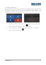
Page 45: ...ressure through each sensor Based on such data arc amount is automatically adjusted A change in arc amount due to abrasion of the electrodes or the fiber splice however is not automatically adjusted T...

Page 46: ...and insert SM fiber into the splicer using clamps or proper fiber holders ii Press as follows iii When arc calibration completes the following screen is displayed iv Press to stop arc before calibrati...

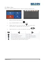
Page 47: ...nction to facilitate dust examination LED examination motor test and calibration Test item Description 1 Dust Testing Conducts dust test without fiber 2 LED Testing Conducts LED test without fiber 3 M...

Page 48: ...tor selection by pressing The name of the selected motor is indicated at the top of the screen iv Operate the motor in a direction wanted by pressing Motor X Y Moves fiber down Moves fiber up ZL Moves...

Page 49: ...he splice operation or any abnormality is incurred while in the entering position the motor setting can be automatically calibrated through this function i Prep and insert SM fiber into the splicer us...

Page 50: ...s mode press and then select ELECTRODE menu with the button The splicer should be regularly cleaned due to electrode abrasion and precipitation of silica oxide This menu is related to checking electro...

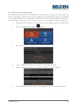
Page 51: ...ant to wait for the electrodes inside to be stabilized After replacing the electrodes in particular stabilizing should be conducted i Prep and insert SM fiber into the splicer using clamps or proper f...

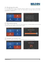
Page 52: ...t number of times for replacement a message about an electrode replacement is displayed 6 6 3Electrodes caution The number of electrodes used is set on this menu It is recommended that electrodes be r...

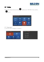
Page 53: ...PX106545 EN Rev A 51 6 7 Setting Display the setting mode by pressing and then select SETTING menu with the button 6 7 1Language A screen to select a language is displayed...

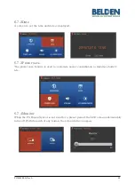
Page 54: ...ayed 6 7 3Power save The power save feature is used to customize power consumption to maximize battery life 6 7 4 Monitor When the FX Fusion Splicer is not used for a preset period the LCD screen auto...

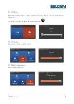
Page 55: ...When the FX Fusion Splicer is not used for the preset period power is automatically turned off The power is turned on again only when pressing 6 7 6 Volume Adjusts the volume of notifications 6 7 7LCD...

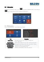
Page 56: ...Description Produce Date Describes the date of the equipment s manufacture year month day Electric Number Indicates the number of the arc after electrode replacement Total Electric Number Indicates t...

Page 57: ...to display the screen below Splicer has sensors to check the temperature air pressure and voltage 6 8 3 Version Press VERSION to display the screen below The version can be upgraded easily by connecti...

Page 58: ...to display the screen below Item Description THE NAMES OF PARTS Names of each component on the FX Fusion Splicer CLEAN AND INSPECT Cleaning and inspection method WARNING S Important warnings A S CONT...

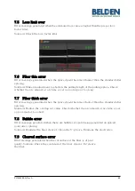
Page 59: ...ains foreign substances that exceed a normal level Solution Repeat splice after cleaning the fiber 7 2 Replace fiber Error message generated when the fiber is not located properly or there is a foreig...

Page 60: ...ED is not bright enough Solution Press and reposition fiber Clean the object lens and reflector Conduct an LED test If an error occurs upon performing the LED test contactBelden 7 4 Fiber over angle E...

Page 61: ...too large or too long 7 7 Fiber thick error Error message generated when the spliced point becomes thicker than the standard after splicing Solution Reduce the overlap set value Check whether the arc...

Page 62: ...e condition When an electrode contains an abrasion or its tip is bent and dirty replace the electrodes Arc amount and arc time are inappropriate Check the setting of arc amount and arc time to reset t...

Page 63: ...for long term use replace it with approved replacement Battery wattage drops with low temperature and more rapidly with temperatures below zero Also splice current consumption goes up with high tempe...

Page 64: ...se recovery measures contact Belden Annual maintenance is required to maintain optimal splice quality The monitor is suddenly turned off Refer to Monitor sleep mode menu Power is suddenly turned off R...

Page 65: ...emove it by pushing it with a cotton swab Initialize heater mode condition Refer to Heat mode edition Cancel heater in the middle of an operation Heater operation cannot cancel by pressing Cancel it b...

Page 66: ...y and contact information Name department company address contact information fax email ii Product serial number iii Product condition and problem incurred errorinformation iv Operating conditions pro...

Reviews: