30
RollNet
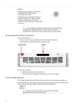
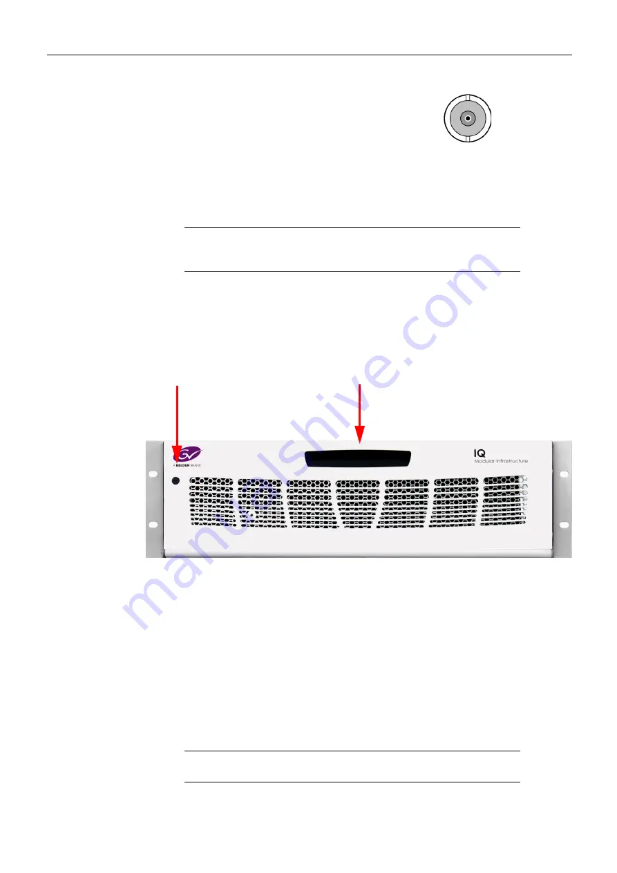
Opening and Closing the Front Panel
To open the front panel:
1 Turn the locking screw approximately half a turn to release the panel.
2 Pull the panel forward and downward using the handle.
To close the front panel:
1 Pull the panel upwards using the handle.
2 Turn the locking screw approximately half a turn to secure the panel.
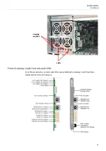
Power Standby Switches
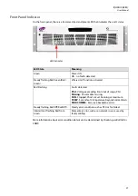
The standby switches are located below the handle on the front of each power supply unit.
On each PSU there is a pair of LEDs. The left LED in each pair indicates the state of the PSU fan.
The right LED of each pair indicates the state of the PSU output power.
•
Green
: OK
•
Red
: Fail
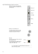
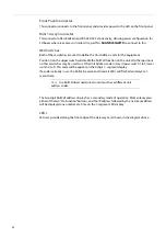
The BNC connector enables the unit to be
connected to the RollCall network
communications system.
The RollCall system should be connected
using a 75 Ohm “T” or “Y” piece, in a similar
manner to an “Ethernet” system. Both
extremities of the system must be terminated
in 75 Ohms.
Note:
The coaxial link is bi-directional and therefore must not be passed
through signal switching networks. Also, to allow hum and noise
cancellation, the screen of the coaxial connection must not be earthed.
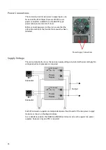
Locking Screw
Handle
Note:
The LEDs will be red if the PSU is unpowered or on standby,
provided that the other PSU is functioning.
Summary of Contents for grass valley IQH3B Series
Page 1: ...User Manual Issue 3 Revision 1 2019 07 12 IQH3B IQH3BQ IQ 3U MODULAR ENCLOSURE ...
Page 14: ...xiv Notices ...
Page 18: ...xviii Table of Contents ...
Page 22: ...22 ...
Page 84: ...84 ...
Page 88: ...88 ...

